


PN25

Yoshitake GP-1010T pilot-operated pressure reducing valve for air and non-corrosive gases. Features a brass/NBR valve, 0.1-1.0 MPa inlet pressure, zero seat leakage, and JIS Rc screwed connection.
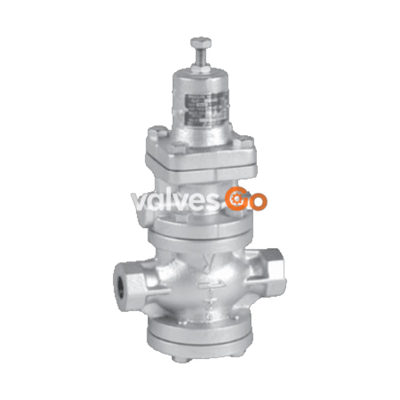
Yoshitake GP-1010T Series pressure reducing valves for air and non-corrosive gases are pilot-operated valves which can be used with confidence for small to large flow rates, in a host of applications ranging from building utilities systems, air-conditioning systems, and factory systems.
| Model | GP-1000T | GP-1010T | GP-1200T | GP-1210T |
|---|---|---|---|---|
| Connection | Flanged (JIS 10K FF) | JIS Rc screwed | Flanged (JIS 10K FF) | JIS Rc screwed |
| Nominal size | 15~100A | 15~50A | 15~100A | 15~50A |
| Application | Air and non-corrosive gases | Air and non-corrosive gases | Air and non-corrosive gases | Air and non-corrosive gases |
| Control type | Spring type | Spring type | Air-loaded type | Air-loaded type |
| Inlet pressure | 0.1-1.0 MPa | 0.1-1.0 MPa | 0.1-1.0 MPa | 0.1-1.0 MPa |
| Reduced pressure | 0.05-0.9 MPa | 0.05-0.9 MPa | 0.05-0.9 MPa | 0.05-0.9 MPa |
| Min. differential pressure | 0.05 MPa | 0.05 MPa | 0.05 MPa | 0.05 MPa |
| Max. pressure reducing ratio | 20:1 | 20:1 | 20:1 | 20:1 |
| Max. temperature | 80°C | 80°C | 80°C | 80°C |
| Valve seat leakage | Zero | Zero | Zero | Zero |
Note: Available with stainless steel made trim parts (piston, cylinder and valve) as GP-TS.
Caution
Please collate with attached nameplate and specification of ordered model. Please consult factory in case they do not match each other.
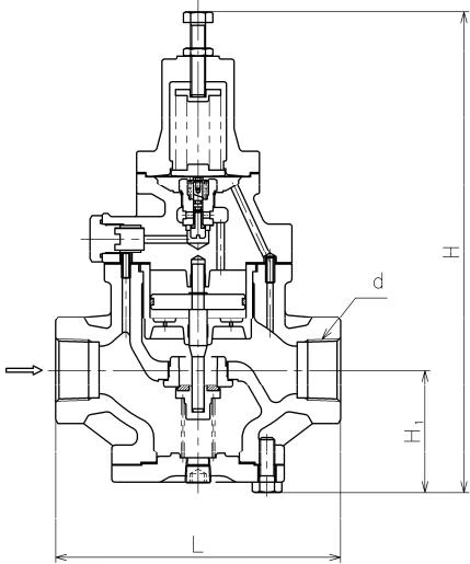
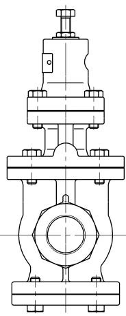
| Size | d | L | H | H1 | Weight (kg) |
|---|---|---|---|---|---|
| 15A | Rc 1/2 | 150 | 285 | 64 | 7.0 |
| 20A | Rc 3/4 | 155 | 285 | 64 | 7.0 |
| 25A | Rc 1 | 160 | 300 | 67 | 8.5 |
| 32A | Rc 1-1/4 | 190 | 323 | 82 | 12.0 |
| 40A | Rc 1-1/2 | 190 | 323 | 82 | 12.5 |
| 50A | Rc 2 | 220 | 347 | 93 | 18.0 |
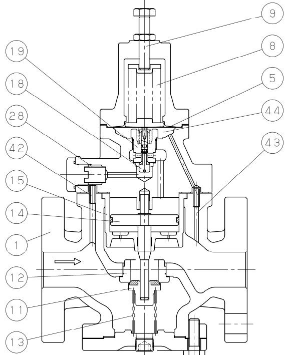
| No. | Parts name |
|---|---|
| 1 | Body |
| 5 | Diaphragm |
| 8 | Adjusting spring |
| 9 | Adjusting screw |
| 11 | Main valve |
| 12 | Main valve seat |
| 14 | Piston |
| 15 | Cylinder |
| 18 | Pilot valve |
| 19 | Pilot valve seat |
| 28 | Strainer |
| 42 | Inlet press. passage |
| 43 | Reduced press. Sensing port |
| 44 | Diaphragm chamber |
The pressure reducing valve reduces pressure by throttling the valve. The valve is composed of the main valve and main valve seat for throttling, and adjusting spring (air-loaded pressure when the remote control type is used), diaphragm, pilot valve, and piston for pressure sensing and activation.
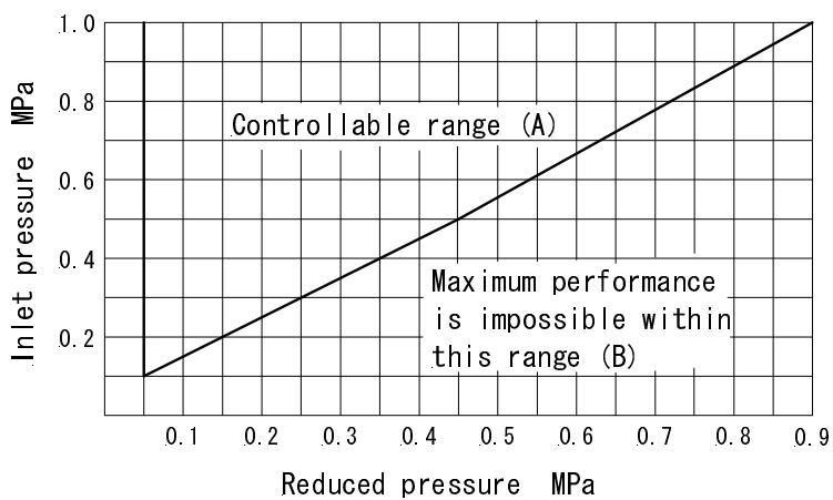 Find the intersection point of the inlet and reduced pressures. The GP-1000T series valves are suitable within range (A). When within range (B), maximum performance cannot be obtained.
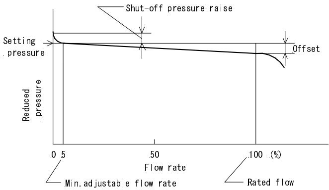
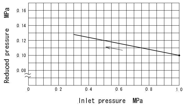
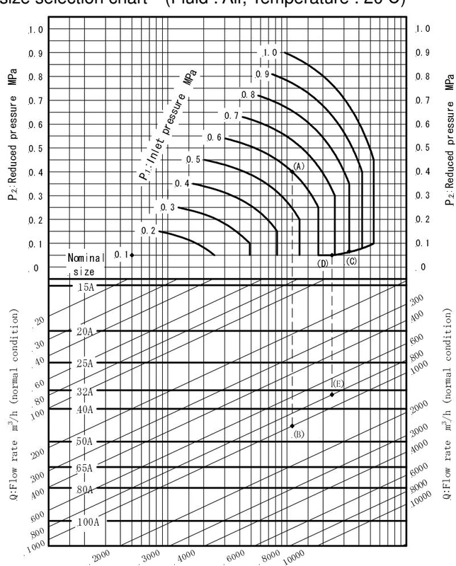
Warning
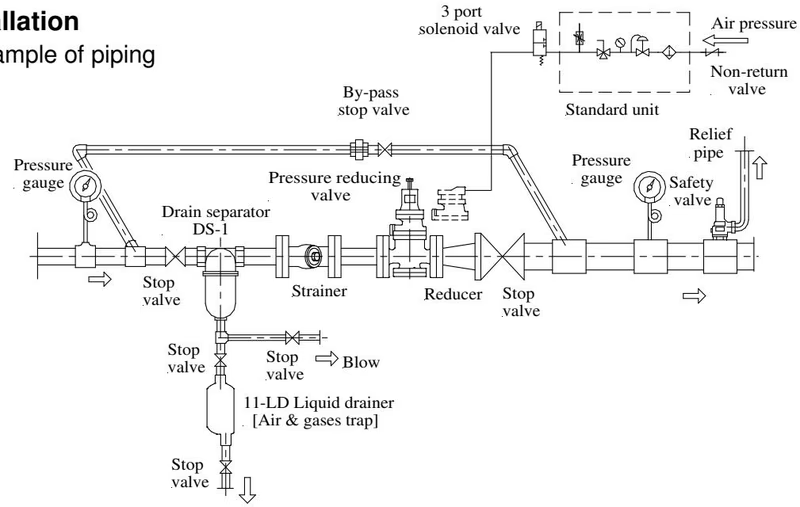
Precautions
Provide space on the top and bottom of the valve so that the valve can be easily disassembled and inspected.
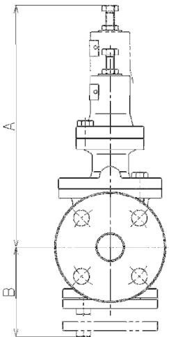
| Nominal size | A (Spring type) | B |
|---|---|---|
| 15A | 310 | 125 |
| 20A | 310 | 125 |
| 25A | 310 | 135 |
| 32A | 330 | 155 |
| 40A | 330 | 155 |
| 50A | 340 | 175 |
(Unit: mm)
Warning
Warning
Completely discharge internal pressure from the valves, lines, and equipment, and cool the valve down to a level where you can touch it with bare hands before disassembly and inspection. When the fluid temperature is high, failure to do so may result in injury or burns due to residual pressure or spillage around the valve.
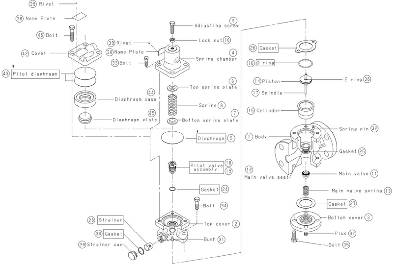
| No. | Name of parts | Replace period |
|---|---|---|
| 5 | Diaphragm | 2 years |
| 16 | O ring | 3 years |
| 18, 19 | Pilot valve assembly | 5 years |
| 24 | Gasket | 5 years |
| 26, 27 | Gasket | 2 years |
| 28 | Strainer | 5 years |
| 30 | Gasket | 2 years |
Note: Apply a liquid sealant for heat and steam resistant (Recommendation: SOLVEST 110) to the sealing surface of the diaphragm bottom and the top cover.
Yoshitake Control Valves / Pressure Reducing Valves
GP, GD, and CP series for stable pressure reduction and control in steam, water, and air systems.
Explore similar products in our catalog



