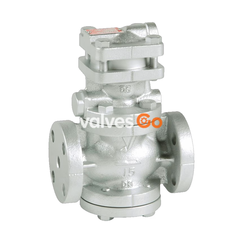
The Yoshitake GP-1200SS is a pilot-operated, pneumatic air-loading pressure reducing valve designed for steam applications. It can be used with confidence for small to large flow rates in a host of applications ranging from building utility systems to factory systems. As a remote-controlled valve, it is exceptionally well-suited for systems where the pressure setting is frequently changed or for centralized control systems. The GP-1200SS features stainless steel wetted parts, providing enhanced durability and improved corrosion resistance.
Features
- Remote Control Application: Ideal for pneumatic and centralized control systems where pressure settings require frequent adjustments via air loading.
- Corrosion Resistance: Improved corrosion resistance with stainless steel wetted parts.
- High Sealability: The spherical main valve offers great sealability and significantly reduces valve seat leakage (compliant with ANSI Class IV).
Specifications
| Specification | Value |
|---|
| Application | Steam |
| Inlet pressure | 0.1 - 1.0 MPa |
| Reduced pressure | 0.05 - 0.9 MPa (90% or less of inlet gauge pressure) |
| Minimum differential pressure | 0.05 MPa |
| Maximum pressure reduction ratio | 20:1 |
| Maximum temperature | 220°C |
| Valve seat leakage | 0.01% or less of rated flow |
| Connection | Flanged (JIS 10K FF) |
Operation
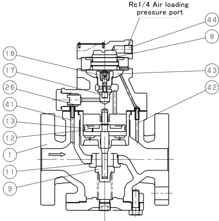
The pressure reducing valve reduces pressure by throttling the main valve. It is composed of the main valve and main valve seat for throttling, alongside an air pressure control space, diaphragm, pilot valve, and piston for pressure sensing and activation.
- When mounted correctly, the main valve and pilot valve remain closed under no air pressure due to spring force. When the gate valve is slowly opened, inlet pressure applies to the downside of the main and pilot valves through the internal strainer and passages.
- Introducing air pressure into the air chamber flexes the pilot diaphragm to open the pilot valve.
- Inlet pressure enters the upside of the piston via the pilot valve, overriding the pressure on the main valve's downside and the main valve spring load, thereby opening the main valve.
- Reduced pressure is routed to the diaphragm chamber, balancing the air loading pressure to control pilot valve travel.
- This balance continuously adjusts the flow rate to the piston, stabilizing the main valve to maintain the set reduced pressure.
Installation & Precautions
Warning
- Heavy Weight: Because of heavy weight, hold the valve with lifting equipment while piping to prevent injury from dropping the valve.
- Safety Relief: If installing a safety valve as a safety device at the outlet side, joint the relief pipe at the outlet of the safety valve and guide it to a safe place where steam can relieve out to prevent burns.
Caution
- Remove all foreign matter and scales from the lines before connecting the valve.
- Install an 80-mesh strainer at the valve inlet side to ensure correct pressure control.
- Install a safety valve at the valve outlet side to protect equipment.
- Install pressure gauges at both the inlet and outlet sides of the valve for correct adjustment.
- Install a steam trap at the inlet side to prevent drainage issues.
- Provide space on the top and bottom of the valve so that it can be easily disassembled and inspected.
- Ensure a bypass line is installed. The secondary pressure at the bypass line must remain lower than the set pressure.
Assembly Drawing & Dimensions
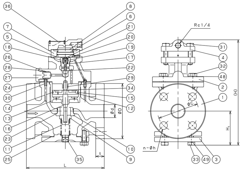
| Nominal Size | L (mm) | H1 (mm) | H (mm) | Weight (kg) |
|---|
| 15A | 150 | 67 | 223 | 8.3 |
| 20A | 155 | 67 | 223 | 8.8 |
| 25A | 160 | 70 | 238 | 10.5 |
| 32A | 190 | 85 | 261 | 14.8 |
| 40A | 190 | 85 | 261 | 15.3 |
| 50A | 220 | 96 | 285 | 20.8 |