


PN25

Yoshitake GP-2000 / GP-2000EN pilot operated pressure reducing valve for steam. Features ductile cast iron body, high Cv value, 20:1 max reduction ratio, and 220°C max temperature.
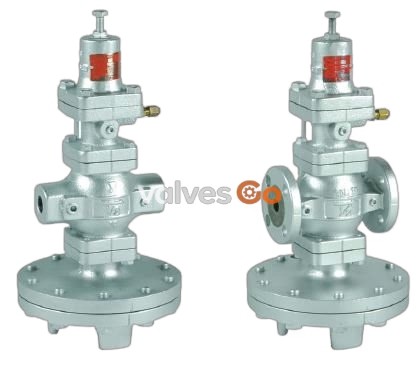
Yoshitake GP-2000 and GP-2000EN are pilot operated pressure reducing valves designed for steam applications. They feature a ductile cast iron body and stainless steel main valve, valve seat, and diaphragm. The standard external sensing method combined with a large-size diaphragm provides highly stable control of reduced pressure.
With a high Cv value, both flow capability and control capability are significantly improved, allowing the use of a nominal size one or two times smaller than conventional valves. The spherical main valve offers excellent sealability, greatly reducing valve seat leakage in compliance with ANSI Class IV.
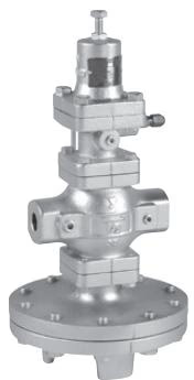
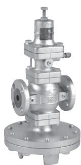
| Specification | GP-2000 | GP-2000EN |
|---|---|---|
| Application | Steam | Steam |
| Reduced Pressure Sensing Method | External sensing *1 | External sensing *1 |
| Inlet Pressure | 0.1 - 2.0 MPa | 0.1 - 1.0 MPa (JIS 10K FF) / 0.1 - 2.0 MPa (JIS 20K, PN25) |
| Reduced Pressure | 0.02 - 0.15 MPa / 0.1 - 1.4 MPa / 1.3 - 1.7 MPa | 0.02 - 0.15 MPa / 0.1 - 0.85 MPa (JIS 10K FF) / 0.1 - 1.4 MPa (JIS 20K, PN25) |
| Minimum Differential Pressure | 0.05 MPa | 0.05 MPa |
| Maximum Pressure Reduction Ratio | 20:1 | 20:1 |
| Maximum Temperature | 220°C | 220°C |
| Valve Seat Leakage | 0.01% or less of rated flow | 0.01% or less of rated flow |
| Body Material | Ductile cast iron | Ductile cast iron |
| Valve / Seat Material | Stainless steel | Stainless steel |
| Diaphragm Material | Stainless steel | Stainless steel |
| Connection | JIS Rc Screw / Flanged (JIS 20K RF, JIS 10K FF) | Flanged (EN PN25) |
INFO
*1 External sensing is standard. When installing the pressure reducing valve, be sure to connect the provided sensing pipe and joint. Internal sensing type (nominal size: 15A to 100A) is available in different specifications. Note that the Cv value of the internal sensing type is lower than that of the external sensing type. GP-2000L is available for reduced pressure of 0.01 to 0.02 MPa (inlet 0.1-0.5 MPa, maximum reduction 50:1).
The pressure reducing valve reduces pressure by throttling the valve. The valve is composed of the main valve and main valve seat for throttling, and adjusting spring, diaphragm, pilot valve, and piston for pressure sensing and activation.
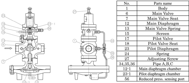
When the pressure reducing valve is mounted correctly, releasing the compression of the adjusting spring allows the main valve spring and pilot valve spring to close the main valve and pilot valve. Slowly open the gate valve to allow high-pressure fluid in. 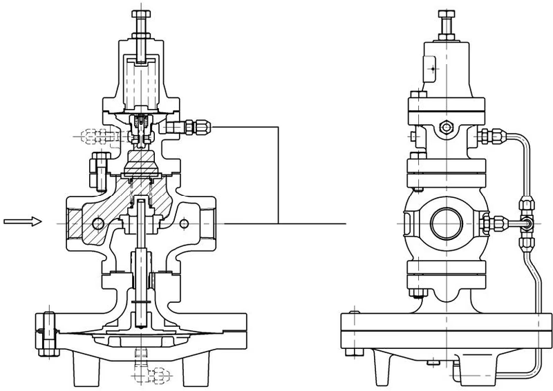
Turning the adjusting screw clockwise compresses the spring, flexing the pilot diaphragm to open the pilot valve. Fluid enters the main diaphragm chamber and also flows to the reduced side of the body via the orifice. 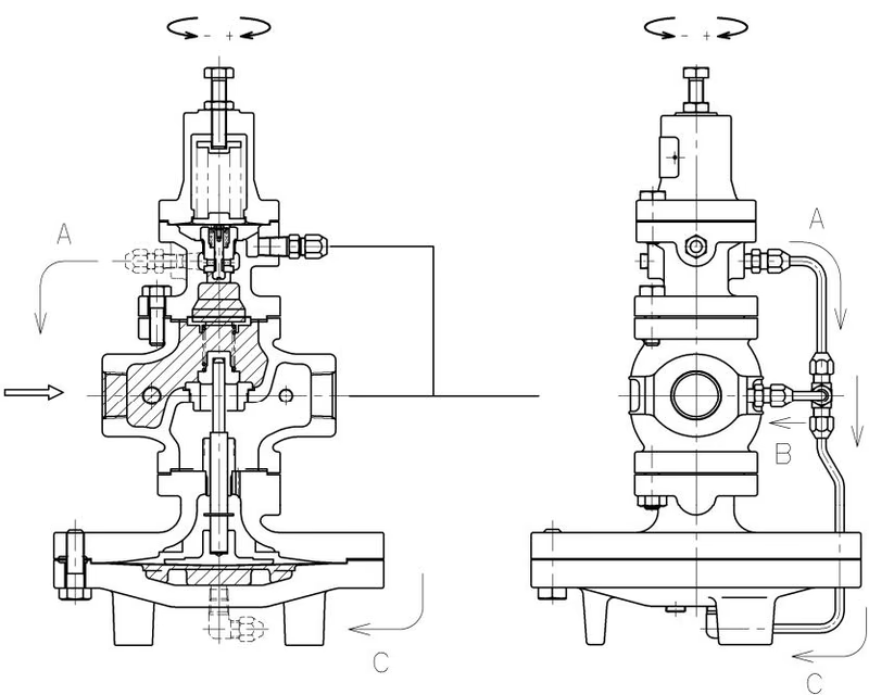
When the flow rate at the pilot valve exceeds the flow rate at the orifice, operating pressure in the main diaphragm chamber rises, overcoming the pressure on the upside of the main valve and opening the main valve. 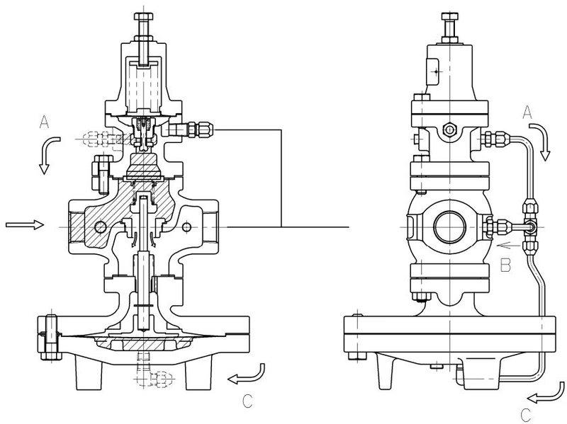
Reduced pressure is led to the pilot diaphragm chamber via the sensing pipe. The pilot diaphragm receives the reduced pressure to be balanced with the spring load. This controls the pilot valve travel and ultimately the main valve travel. 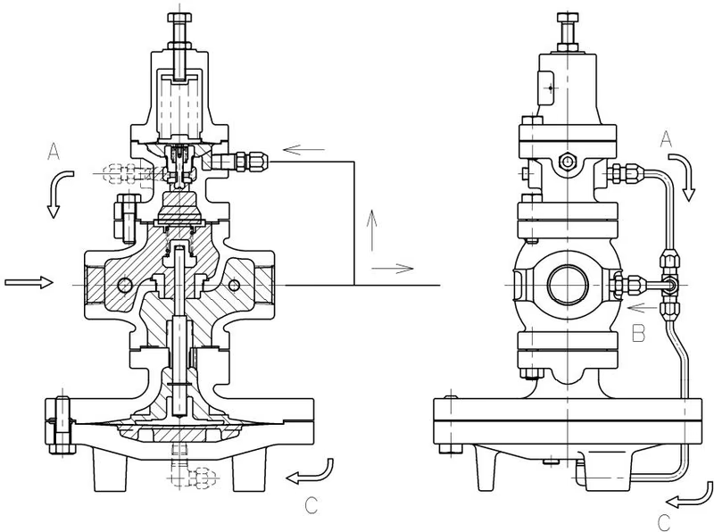
When the load on the reduced side is released, pressure in the pilot diaphragm chamber rises to close the pilot valve. Operating pressure is released to the body, and the main valve closes. 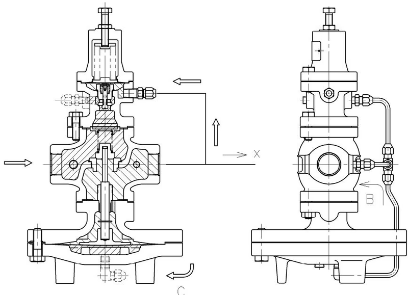
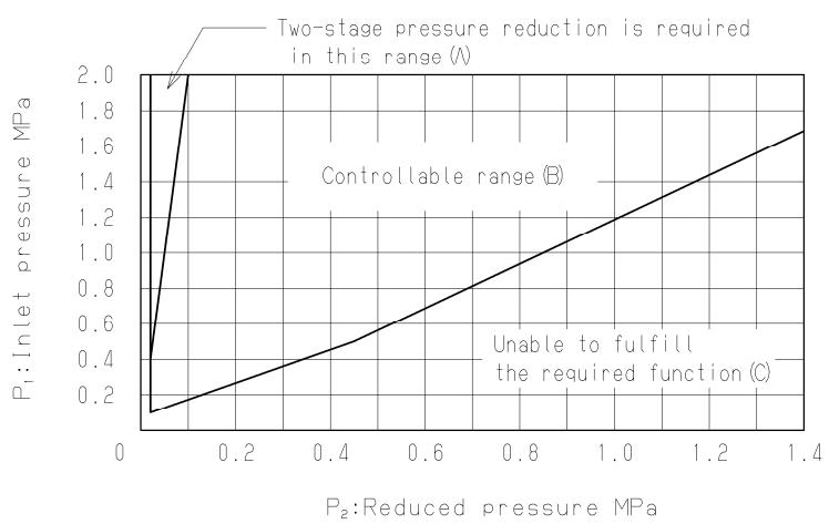
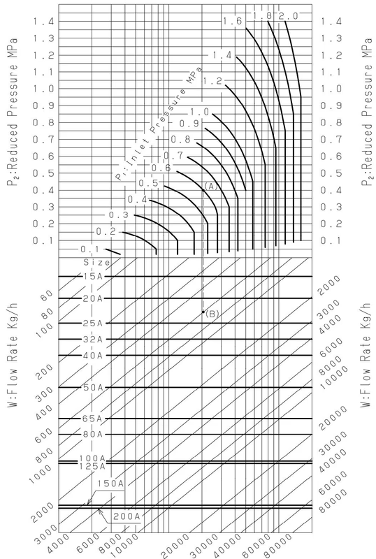
Refer to the selection chart to select the most appropriate pressure reducing valve. Find the point of intersection of inlet pressure (P1) and reduced pressure (P2).
TIP
When the point of intersection is within range (A), reduce pressure in two stages. When reducing pressure in two stages, maximize the distance between the valves (at least 3 m).
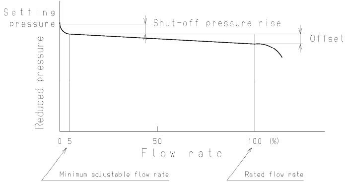
Flow Rate Characteristics Chart
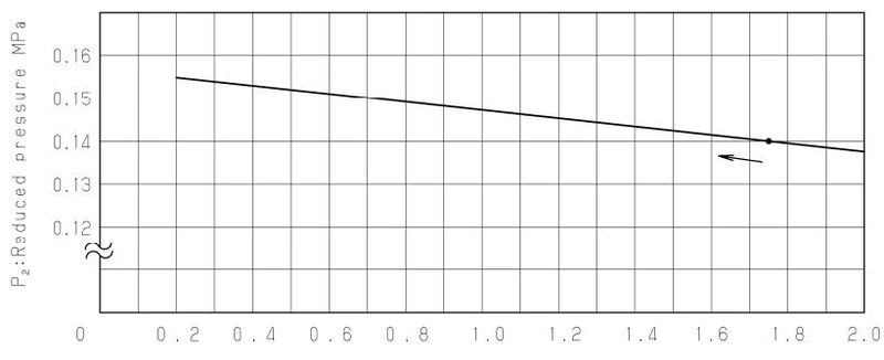
Pressure Characteristics Chart Reduced pressure is set to 0.14 MPa when inlet pressure is 1.75 MPa. The chart indicates a variation in reduced pressure when the inlet pressure is changed from 0.2 to 2.0 MPa.
For example, take a pressure reducing valve whose inlet pressure (P1) is 0.6 MPa, reduced pressure (P2) 0.4 MPa, flow rate 600 kg/h. Find the point of intersection (A) of inlet pressure 0.6 MPa and reduced pressure 0.4 MPa. Vertically proceed to the flow rate 600 kg/h (Point B). Select the larger nominal size.
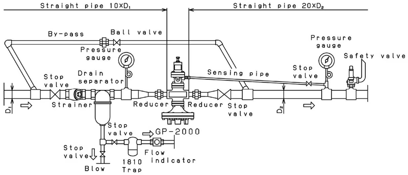
Precautions during installation
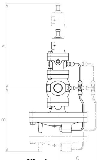
Provide space on the top and bottom of the valve so that the valve can be easily disassembled and inspected.
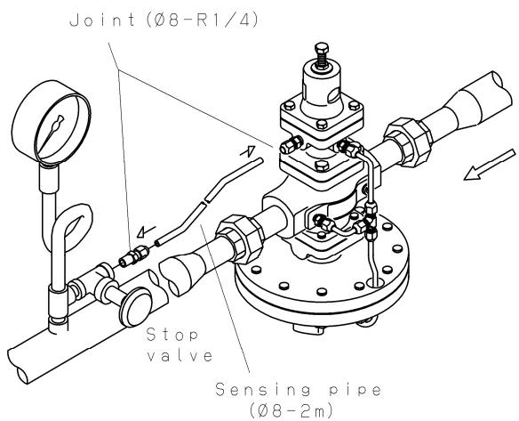
Connect the provided sensing pipe (φ8-2m) and joint (φ8-R1/4) as shown in the illustration. Note that the sensing pipe must be connected so that the valve side is higher than the pressure sensing side.
Yoshitake Control Valves / Pressure Reducing Valves
GP, GD, and CP series for stable pressure reduction and control in steam, water, and air systems.
Explore similar products in our catalog



