


PN25

Yoshitake GP-2000CS pilot-operated diaphragm pressure reducing valve for steam. Features cast carbon steel body, max inlet pressure up to 3.0 MPa, 20:1 reduction ratio, and tight ANSI Class IV sealing.
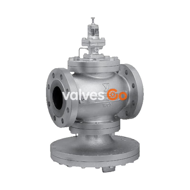
Yoshitake GP-2000CS pressure reducing valve for steam is a pilot-operated diaphragm type valve. It can control a larger flow of fluid than piston types, offering superior controllability for pressure fluctuation of the inlet side or load fluctuation of the outlet side. It can be widely used in building utilities systems, air-conditioning systems, and factory systems.
| Model | GP-2000CS |
|---|---|
| Application | Steam |
| Reduced pressure sensing method | External sensing * |
| Max. inlet pressure | 3.0 MPa / 1.0 MPa / 2.0 MPa |
| Reduced pressure | 0.02-0.15 MPa, 0.1-1.4 MPa, 1.3-2.0 MPa / 0.02-0.15 MPa, 0.1-0.85 MPa / 0.02-0.15 MPa, 0.1-1.4 MPa, 1.3-1.7 MPa |
| Minimum differential pressure | 0.05 MPa |
| Maximum pressure reduction ratio | 20:1 |
| Maximum temperature | 260°C |
| Valve seat leakage | 0.01% or less of rated flow rate |
| Body Material | Cast carbon steel (WCB) |
| Main valve & seat Material | Stellite overlaid stainless steel |
| Pilot valve & seat Material | Stainless steel |
| Diaphragm Material | Stainless steel |
| Connection | JIS Rc screwed, JIS 10K FF flanged, JIS 20K RF flanged, JIS 30K RF flanged, ASME/EN flanged |
INFO
| Nominal size | d | L (mm) | H (mm) | H1 (mm) | Weight (kg) |
|---|---|---|---|---|---|
| 15A | Rc 1/2 | 150 | 398 | 200 | 16.0 |
| 20A | Rc 3/4 | 150 | 398 | 200 | 16.0 |
| 25A | Rc 1 | 160 | 404 | 226 | 21.5 |
| 32A | Rc 1-1/4 | 180 | 434 | 226 | 24.0 |
| 40A | Rc 1-1/2 | 200 | 434 | 226 | 24.0 |
| 50A | Rc 2 | 230 | 498 | 276 | 37.0 |
| Nominal size | L (mm) | H (mm) | H1 (mm) | Weight (kg) |
|---|---|---|---|---|
| 50A | 230 | 498 | 216 | 42.0 |
| 65A | 294 | 552 | 251 | 75.5 |
| 80A | 314 | 575 | 264 | 84.0 |
| 100A | 358 | 658 | 321 | 133.0 |
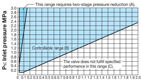
Based on the selection chart above, select a pressure reducing valve in the optimum manner. Find the intersection point of the inlet pressure (P1) and the reduced pressure (P2). Two-stage pressure reduction is required if the intersection point lies in range (A). The pressures are controllable with a single pressure reducing valve if the intersection point is within range (B). The valve does not fulfil specified performance in range (C). To adopt two-stage pressure reduction, separate two pressure reducing valves as far away from each other as possible (at least 3M).
When selecting a nominal size, set the flow rate at 80 to 90% of the rated flow rate, allowing for the pressure loss and heat loss of the stop valve, strainer, etc. to be used before or after the pressure reducing valve.
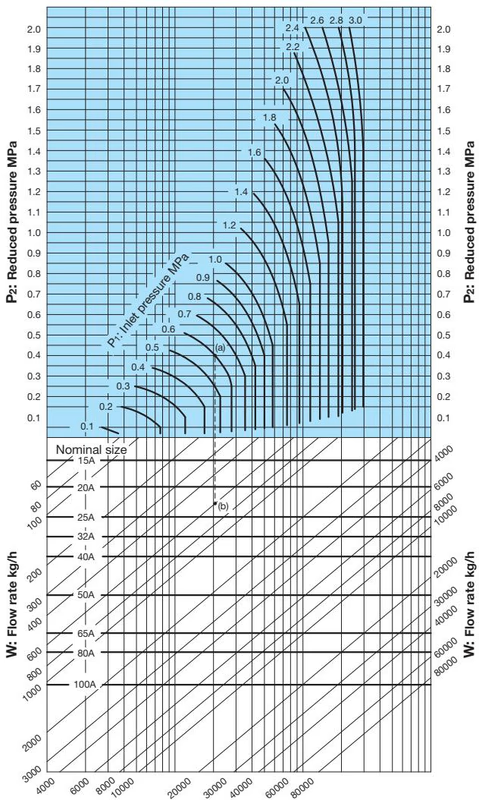
Flow Characteristic Chart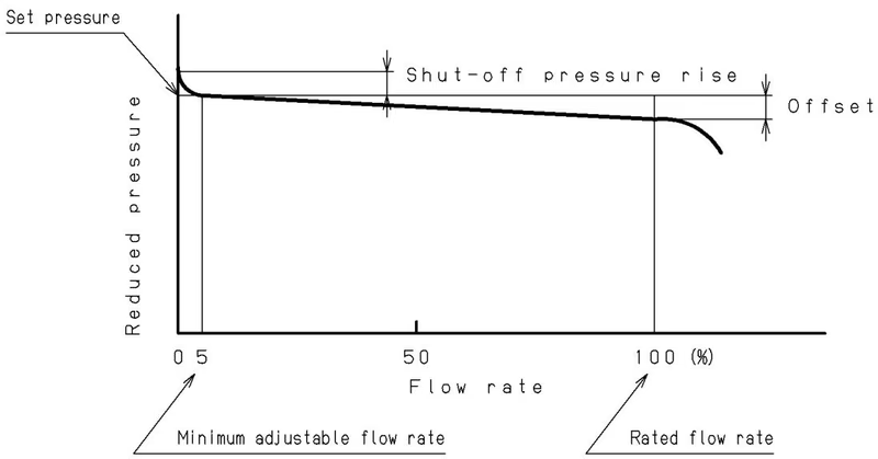 Shut-off pressure rise: 0.02 MPa or less. Offset: 10% or less of setting pressure at outlet side (Minimum value: 0.02 MPa).
Pressure Characteristic Chart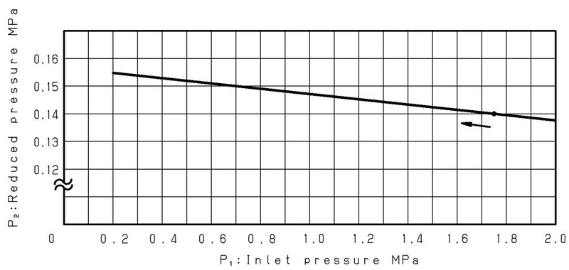 This chart shows variation in reduced pressure when the inlet pressure of 1.75 MPa is changed between 0.2 MPa to 2.0 MPa while the reduced pressure is set at 0.14 MPa.
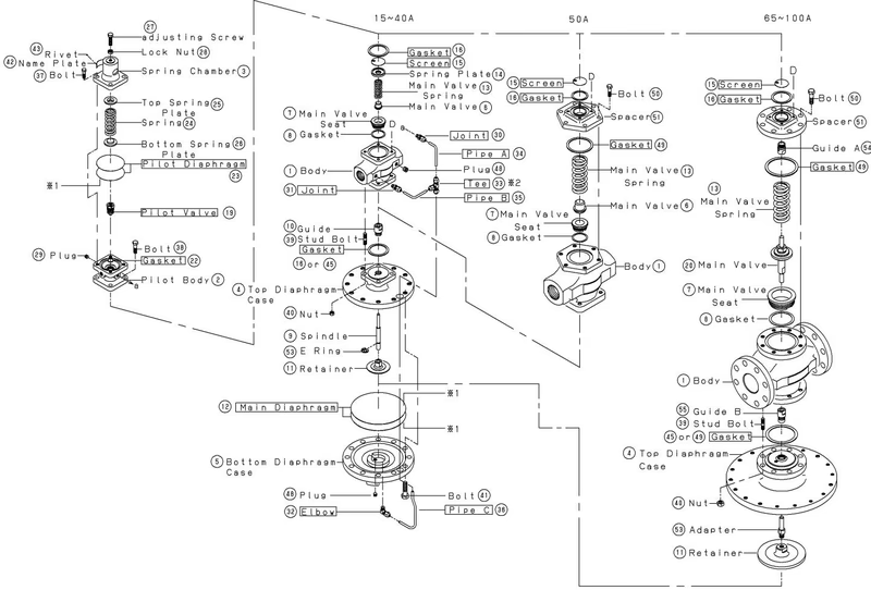
The pressure reducing valve reduces pressure by throttling action, composed of the main valve, main valve seat, adjusting spring, pilot diaphragm, pilot valve, and main diaphragm.
When the adjusting spring is free of load, the main valve and pilot valve are closed. High-pressure fluid applies inlet pressure to the upside of the main valve and downside of the pilot valve. 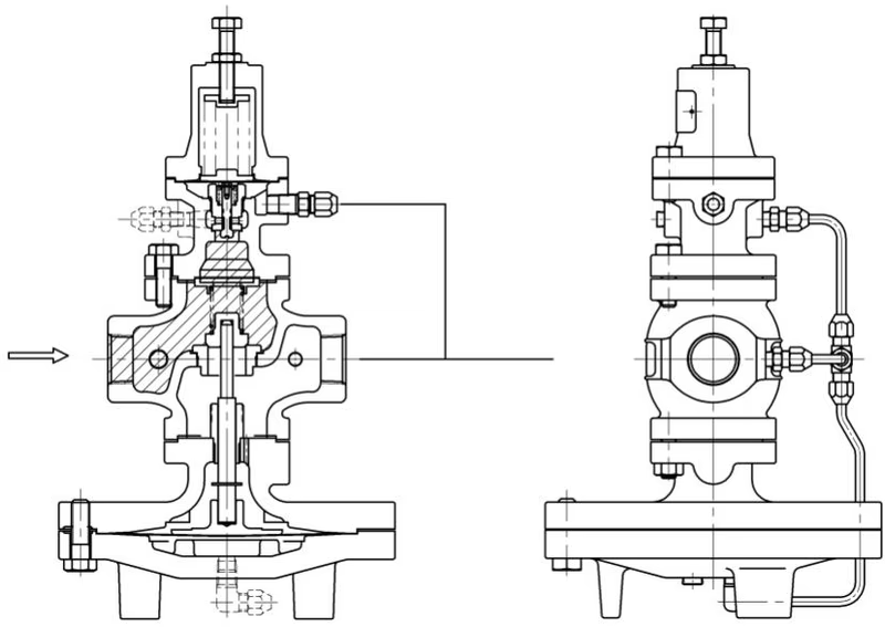
Turning the adjusting screw clockwise compresses the spring, bending the pilot diaphragm to open the pilot valve. Fluid enters the main diaphragm chamber and also flows to the outlet side. 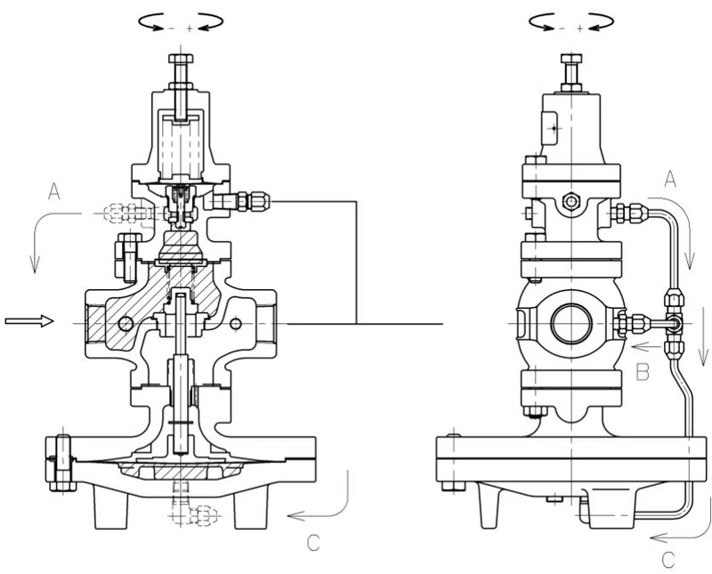
Increased flow through the pilot valve raises operating pressure in the main diaphragm chamber, overriding the main valve spring load and opening the main valve. 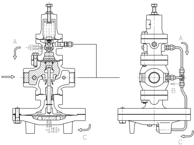
Outlet pressure is led to the pilot diaphragm chamber via the sensing pipe, balancing with the adjusting spring load. The pilot valve travel controls the main valve travel to maintain reduced pressure. 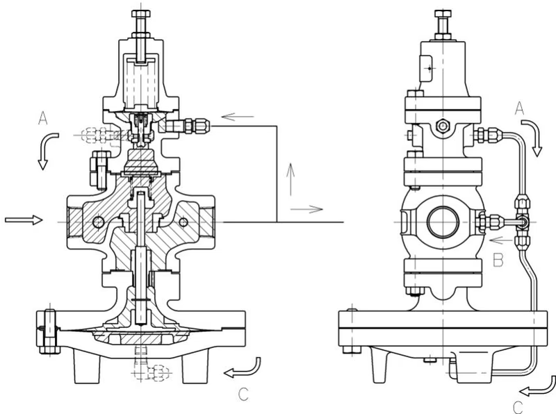
When fluid does not flow at the outlet, pressure in the pilot diaphragm chamber rises to close the pilot valve. The main valve is then closed by the main valve spring. 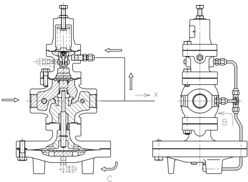
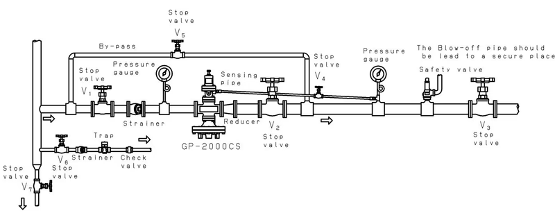
WARNING
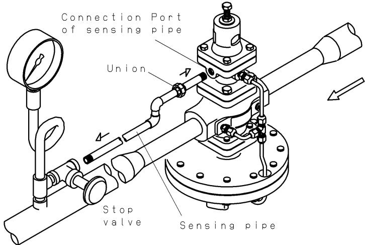
Sensing Pipe Connection Connect the sensing pipe and the joint from the connection port of the product to the outlet piping. Make the connection port of the product be above the level of the side opposite to the connection port of the product. Make the length of the sensing pipe less than 5 meters.
Yoshitake Control Valves / Pressure Reducing Valves
GP, GD, and CP series for stable pressure reduction and control in steam, water, and air systems.
Explore similar products in our catalog



