


PN25

Yoshitake GPK-2003 pilot-operated, remote-controlled pressure reducing valve for steam. Features a spherical main valve, external sensing, and 10:1 reduction ratio.
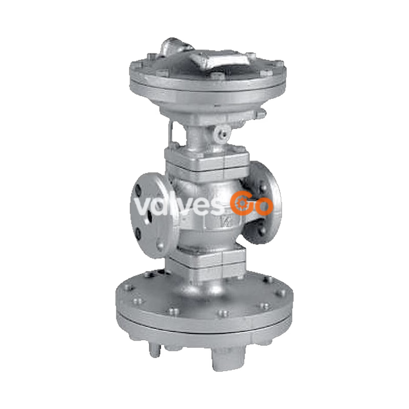
Yoshitake GPK-2003 is a pilot-operated, remote-controlled pressure reducing valve designed for steam applications. It features a spherical main valve that offers excellent sealability and significantly reduces valve seat leakage (compliant with ANSI Class IV). The remote control capability makes pressure adjustment easy and provides a wide pressure setting range. It is superior to piston-type valves in capacity and performance, effectively controlling inlet pressure and flow rate fluctuations. The GPK-2001 model is also available, and the choice between GPK-2001 and GPK-2003 depends on the loading air pressure.
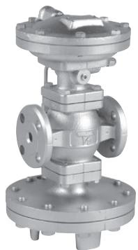
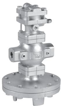
| Model | GPK-2001 | GPK-2003 |
|---|---|---|
| Application | Steam | Steam |
| Reduced pressure sensing method | External sensing * | External sensing * |
| Inlet pressure (JIS Rc, JIS 20K RF) | 0.1-2.0 MPa | 0.25-2.0 MPa |
| Inlet pressure (JIS 10K FF) | 0.1-1.0 MPa | 0.25-1.0 MPa |
| Reduced pressure (JIS Rc, JIS 20K) | 0.05-0.9 MPa | 0.2-1.4 MPa |
| Reduced pressure (JIS 10K) | 0.05-0.85 MPa | 0.2-0.85 MPa |
| Minimum differential pressure | 0.05 MPa | 0.05 MPa |
| Maximum pressure reduction ratio | 20:1 | 10:1 |
| Maximum temperature | 220°C | 220°C |
| Valve seat leakage | 0.01% or less of rated flow | 0.01% or less of rated flow |
| Body Material | Ductile cast iron | Ductile cast iron |
| Main valve / seat | Stainless steel | Stainless steel |
| Pilot valve / seat | Stainless steel | Stainless steel |
| Diaphragm | Stainless steel | Stainless steel |
| Connection | JIS Rc screwed, JIS 20K RF and 10K FF flanged | JIS Rc screwed, JIS 20K RF and 10K FF flanged |
| Nominal size | d | L | H1 | H | A | Weight (kg) GPK-2001 | Weight (kg) GPK-2003 |
|---|---|---|---|---|---|---|---|
| 15A | Rc 1/2 | 150 | 170 | 335 / 353 | 200 | 14.0 | 17.5 |
| 20A | Rc 3/4 | 150 | 170 | 335 / 353 | 200 | 14.0 | 17.5 |
| 25A | Rc 1 | 160 | 175 | 341 / 359 | 226 | 18.5 | 22.0 |
| 32A | Rc 1-1/4 | 180 | 192 | 371 / 389 | 226 | 21.5 | 25.0 |
| 40A | Rc 1-1/2 | 180 | 192 | 371 / 389 | 226 | 21.5 | 25.0 |
| 50A | Rc 2 | 230 | 216 | 435 / 453 | 276 | 33.0 | 36.5 |
| Nominal size | L | H1 | H (GPK-2001/2003) | A | Weight (kg) GPK-2001 | Weight (kg) GPK-2003 |
|---|---|---|---|---|---|---|
| 15A | 146 | 170 | 335 / 353 | 200 | 15.5 | 19.0 |
| 20A | 146 | 170 | 335 / 353 | 200 | 16.0 | 19.5 |
| 25A | 156 | 175 | 341 / 359 | 226 | 21.0 | 24.5 |
| 32A | 176 | 192 | 371 / 389 | 226 | 24.0 | 27.5 |
| 40A | 196 | 192 | 371 / 389 | 226 | 24.5 | 28.0 |
| 50A | 222 | 216 | 435 / 453 | 276 | 36.0 | 39.5 |
| 65A | 282 | 251 | 489 / 507 | 352 | 64.5 | 68.0 |
| 80A | 302 | 264 | 512 / 530 | 352 | 71.5 | 75.0 |
| 100A | 342 | 321 | 595 / 613 | 401 | 111.0 | 114.5 |
The pressure reducing valve reduces pressure by throttling the valve. The valve is composed of the main valve, main valve seat, a pressure adjusting air chamber, and the main diaphragm, pilot diaphragm, and pilot valve for pressure sensing and activation.
Refer to the selection chart to select the most appropriate pressure reducing valve. Find the point of intersection of inlet pressure (P1) and reduced pressure (P2). When the point of intersection is within range (A), reduce pressure in two stages. When within range (B), controllable range. When within range (C), maximum performance cannot be obtained.
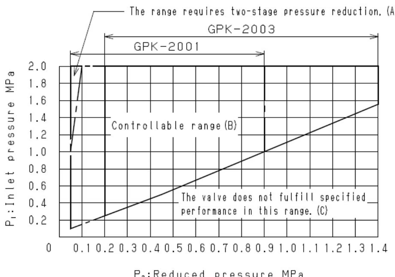
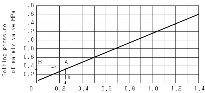
Determine the reduced pressure of pressure reducing valve. Find the intersection point (A) with the chart curve. Next, find point (B) by proceeds horizontally from point (A) to the left until the ‘Setting pressure of safety valve’ axis. The setting pressure of the safety valve should be higher than the pressure of the point (B).
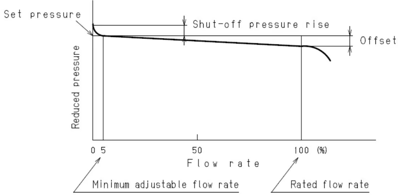
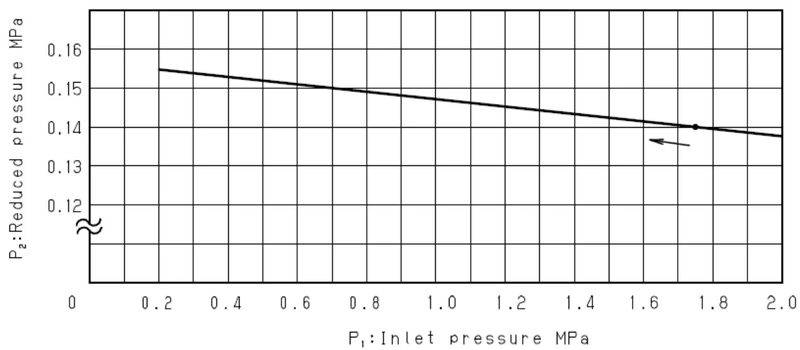
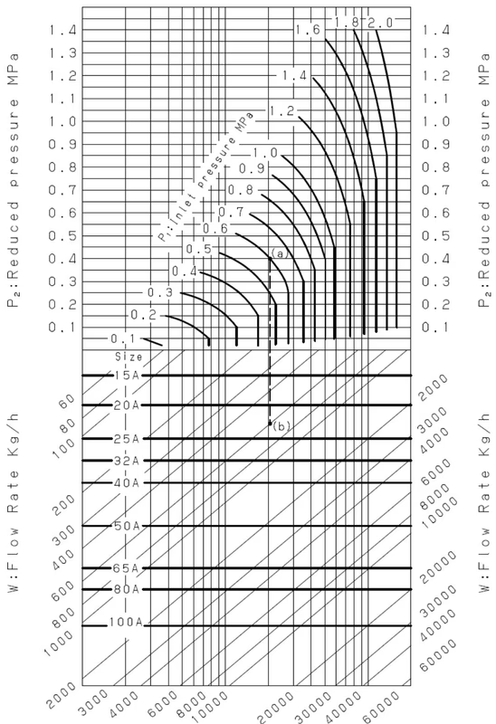
An appropriate nominal size can be calculated by obtaining Cv value for the operating conditions in question.
Rated Cv value table (External sensing)
| Nominal size | 15A | 20A | 25A | 32A | 40A | 50A | 65A | 80A | 100A |
|---|---|---|---|---|---|---|---|---|---|
| Cv value | 5.0 | 7.2 | 10.9 | 14.3 | 18.8 | 32 | 54 | 70 | 108 |
WARNING
Since the product is heavy, securely support it using lifting devices or the like when installing. Failure to follow this notice may cause falling accident of the product, resulting in bodily injury.
TIP
When installing the pressure reducing valve, be sure to connect the provided sensing pipe and joint. Unless the sensing pipe is connected, the valve will not operate. Further, steam may blow off, resulting burns.
| Problem | Cause | Solution |
|---|---|---|
| Pressure does not reach the desired value. | Incorrect pressure is being used. Insufficient operating air pressure. Screen is clogged. Main diaphragm is damaged. | Correct the pressure. Increase the operating air pressure. Disassemble and clean the screen. Replace the main diaphragm. |
| Reduced pressure raises above than the specified value. | Operating air pressure too high. Foreign matter exists between main valve and main valve seat. | Decrease the operating air pressure. Disassemble and remove the foreign matter. |
| Abnormal noise is heard. | Orifice of tee is clogged. Nominal size is too large for the specifications. Pressure reducing ratio is too large. | Remove the tee and clean it. Change the nominal size appropriately. Reduce pressure in two stages. |
WARNING
Completely discharge internal pressure from the valves, lines, and equipment, and cool the valve down to a level where you can touch it with bare hands before disassembly and inspection.
Yoshitake Control Valves / Pressure Reducing Valves
GP, GD, and CP series for stable pressure reduction and control in steam, water, and air systems.
Explore similar products in our catalog



