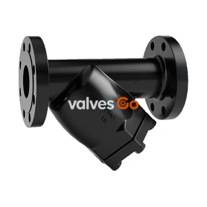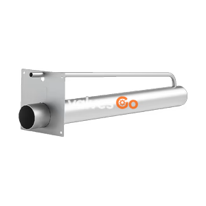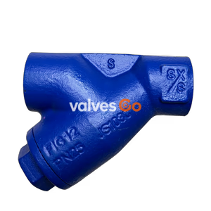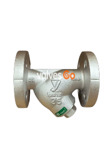
Ductile Cast Iron

Yoshitake SU-6, SU-6SS, and SU-6AS Y-Type Strainers for cold and hot water, oil, and non-dangerous fluids. Maximum pressure 1.0 MPa, max temperature 120°C.
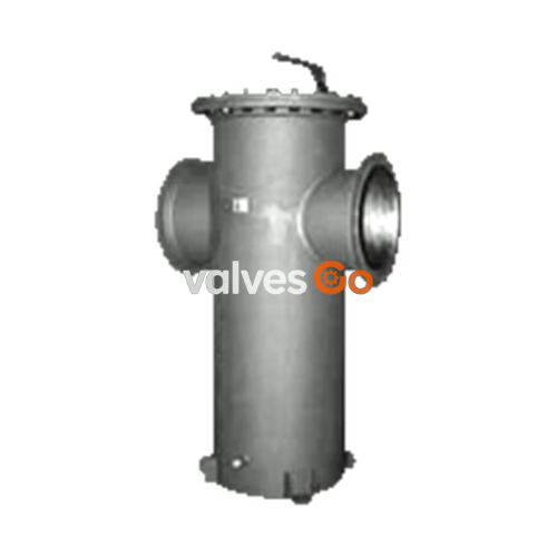
Yoshitake SU-6, SU-6SS, and SU-6AS are Y-type strainers mainly used for cooling water and industrial water for dust prevention. They are designed for large-diameter piping and are lighter than cast iron strainers. The strainers are available with 20 to 100 mesh screens and can be ordered with rust-proof (hot-dip zinc coating) for the SU-6 models.
| Model | SU-6 | SU-6SS | SU-6AS |
|---|---|---|---|
| Application | Cold and hot water, Oil, Other non-dangerous fluids | Cold and hot water, Oil, Other non-dangerous fluids | Cold and hot water, Oil, Other non-dangerous fluids |
| Nominal Size | 150A-650A | 150A-650A | 200A-650A |
| Maximum Pressure | 1.0 MPa | 1.0 MPa | 1.0 MPa |
| Maximum Temperature | 120°C | 120°C | 120°C |
| Body Material | Carbon steel pipe and rolled steel | General structural rolled steel and stainless steel | Stainless steel |
| Screen Material | Stainless steel | Stainless steel | Stainless steel |
| Screen Perforation | φ6-8P (150A), φ10-12.5P (200-650A) | φ10-12.5P | φ10-12.5P |
| Screen Mesh | Standard 40 mesh | Standard 40 mesh | Standard 40 mesh |
| Connection | JIS 10K FF flanged | JIS 10K FF flanged | JIS 10K FF flanged |
Caution
Please confirm that the indications on the product plate coincide with the specifications of the ordered model. Also confirm that the conditions for usage coincide with the Specifications. In case they do not coincide, do not use the product and contact us.
Dust, scale and other foreign matter from the fluid flowing into the strainer through the inlet port are removed by the screen.
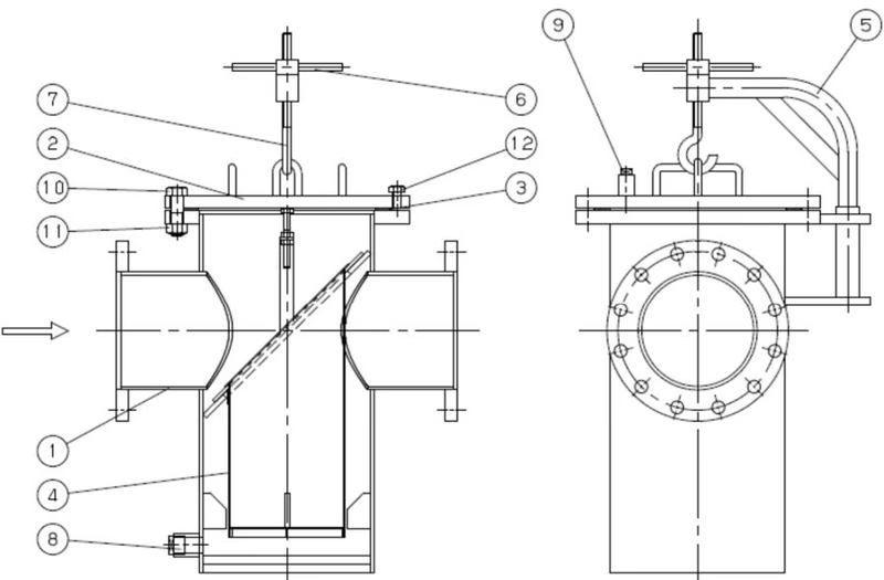
| No. | Part Name |
|---|---|
| 1 | Body |
| 2 | Cover |
| 3 | Gasket |
| 4 | Screen |
| 5 | Davit Pipe |
| 6 | Handle |
| 7 | Hanger Rod |
| 8 | Plug |
| 9 | Plug |
| 10 | Bolt |
| 11 | Nut |
| 12 | Bolt |
*The structure differs depending on the nominal size.
The nominal size of the strainer should be the same as that for the piping. Please note that if the nominal size of the strainer is smaller than that for the piping, the pressure loss of the strainer may grow, resulting in failure to maintain the required pressure at the inlet of the equipment.
The Japanese Industrial Standard (JIS F 7101) designates the standard flow velocity for piping by type and features of the fluid and pipe size.
Standard flow velocity by fluid
| Fluid | Standard velocity |
|---|---|
| Water & oil | 2 m/s (2 - 4) |
Pressure Loss Chart for Model SU-6 Strainer (for Water) Screen: φ10-12.5P and 40-mesh 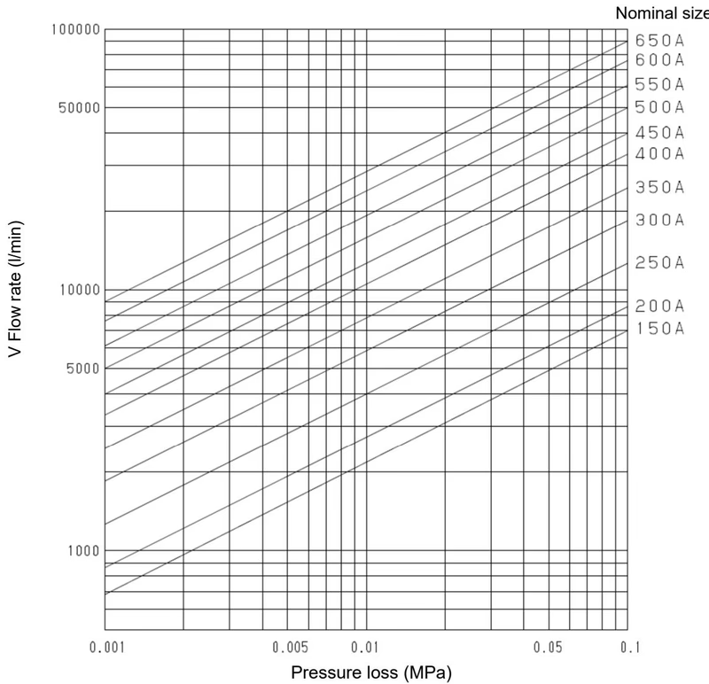
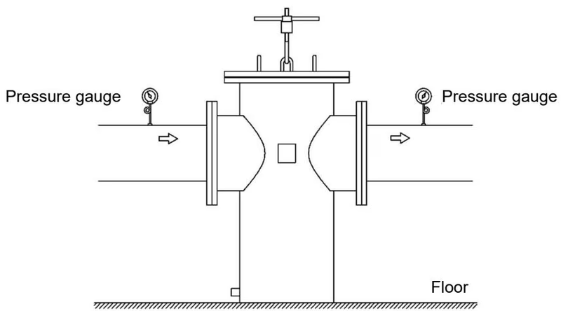
Warning
Maintenance and Inspection Space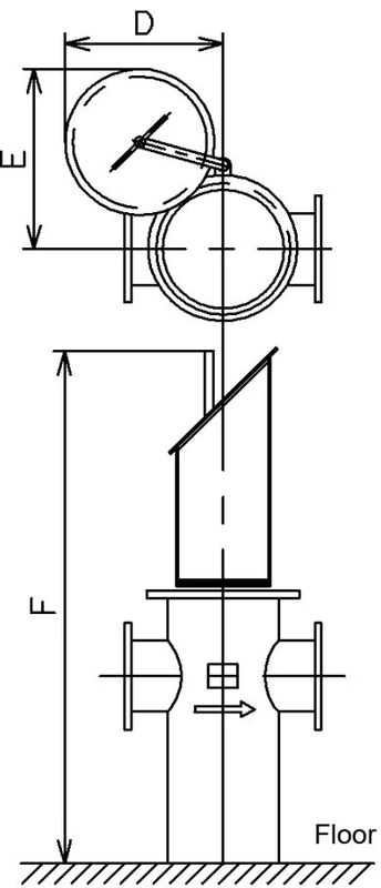
| Nominal Size | D (mm) | E (mm) | F (mm) |
|---|---|---|---|
| 150A | 454 | 430 | 1190 |
| 200A | 496 | 482 | 1205 |
| 250A | 540 | 540 | 1565 |
| 300A | 610 | 628 | 1860 |
| 350A | 656 | 715 | 2020 |
| 400A | 737 | 766 | 2290 |
| 450A | 800 | 855 | 2585 |
| 500A | 847 | 924 | 3271 |
| 550A | 894 | 995 | 3581 |
| 600A | 950 | 1078 | 3801 |
| 650A | 1017 | 1153 | 4151 |
Caution
| Condition of Failure | Causes | Measures and Treatment |
|---|---|---|
| Fluid does not flow. | 1. Screen is clogged. 2. The stop valves at either end of the strainer are closed. | 1. Disassemble the strainer and clean screen. 2. Open the stop valves. |
| Pressure loss is high. | 1. Screen is clogged. 2. Pressure gauge is out of order. 3. The nominal size is too small for the actual flow rate. | 1. Disassemble the strainer and clean screen. 2. Exchange the pressure gauge. 3. Use a strainer with a larger nominal size. |
Warning
After checking that there is no residual pressure in the strainer, disassemble it with the following procedures.
Assemble the product with the opposite procedures of disassembly. When assembling, replace the gasket with a new one and evenly tighten bolts in the diagonally opposite directions to prevent uneven tightening.
Cover Nut Tightening Torque (for reference)
| Nominal Size | Nominal Nut Size | Standard Tightening Torque in N-m |
|---|---|---|
| 200A, 250A | M22 | 300 |
| 300A, 350A, 400A | M24 | 400 |
| 450A, 500A, 550A, 600A, 650A | M30 | 700 |
TIP
As the cover nut tightening torques are large, it is recommended to use a power tool (impact wrench or so) capable of tightening to such torques for disassembly and assembly.
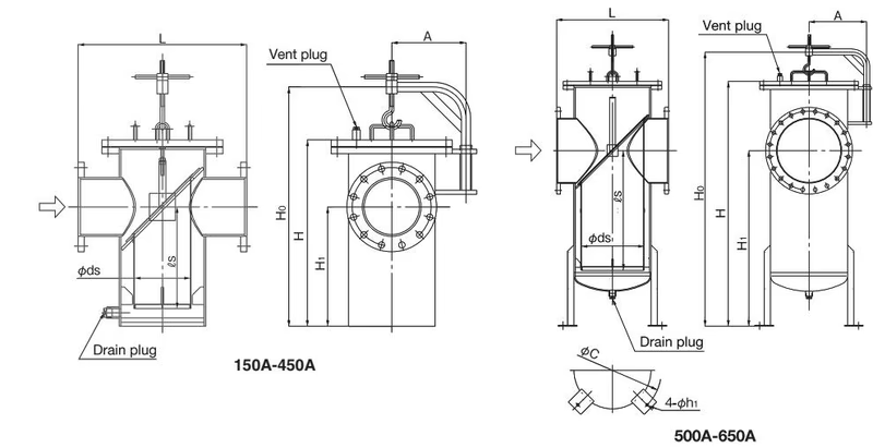
| Nominal Size | L | A | Ho | H | H1 | ds | ls | Vent plug | Drain plug | Weight (kg) |
|---|---|---|---|---|---|---|---|---|---|---|
| 150A | 500 | 284 | 830 | 630 | 410 | 200 | 370 | R 1/2 | R 1/2 | 135 |
| 200A | 620 | 273 | 882 | 687 | 440 | 210 | 375 | R 1/2 | R 1 | 130 |
| 250A | 660 | 295 | 1062 | 867 | 570 | 240 | 505 | R 1/2 | R 1 | 185 |
| 300A | 710 | 330 | 1218 | 1021 | 670 | 290 | 600 | R 1/2 | R 1 | 240 |
| 350A | 760 | 350 | 1306 | 1103 | 710 | 340 | 640 | R 3/4 | R 1 | 310 |
| 500A | 910 | 455 | 2195 | 1945 | 1400 | 490 | 930 | R 1 | R 1 1/2 | 650 |
| 550A | 960 | 480 | 2353 | 2107 | 1510 | 540 | 1030 | R 1 | R 1 1/2 | 780 |
| 600A | 1010 | 510 | 2538 | 2237 | 1590 | 590 | 1100 | R 1 | R 1 1/2 | 930 |
| 650A | 1060 | 545 | 2716 | 2419 | 1720 | 640 | 1170 | R 1 | R 1 1/2 | 1100 |
*Dimensions H1 and Ho are reference values. Dimensional values for additional sizes are shown where OCR data permitted extraction.
Yoshitake Instrumentation / Strainers
SY, SU, SW, and ST series strainers for removing line debris and protecting downstream valves and equipment.