Ductile Cast Iron

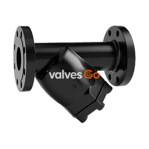
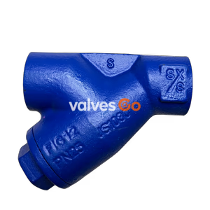
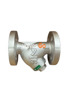
Yoshitake SY-40H Y-type strainer features ductile cast iron body and stainless steel screen. Max pressure 2.0 MPa, temp 220°C. Ideal for steam, air, and water.
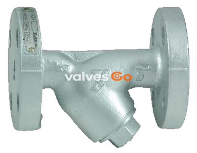
Yoshitake SY-40H Y-type strainer features a ductile cast iron body and stainless steel screen, designed for steam, air, hot or cold water, and other non-dangerous fluids. It provides a maximum operating pressure of 2.0 MPa and withstands maximum temperatures up to 220°C. The strainer is built with the largest possible filtration area as a countermeasure against flow rate decreases caused by clogging.
| Model | SY-40H |
|---|---|
| Application | Steam, air, hot or cold water, and other non-dangerous fluids |
| Maximum pressure | 2.0 MPa |
| Maximum temperature | 220°C |
| Material (Body) | Ductile cast iron |
| Material (Screen) | Stainless steel |
| Standard Screen Perforations | φ2.5-4P |
| Standard Screen Mesh | 80 mesh |
| Connection | JIS 20K FF flanged, ASME Class 300 flanged |
INFO
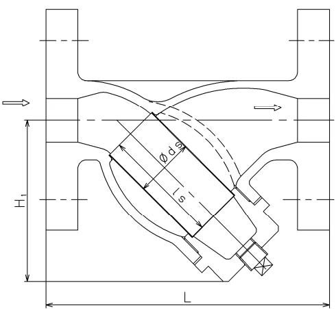 Figure 1: 15-50A (No plug is provided with 15 to 32A ones)
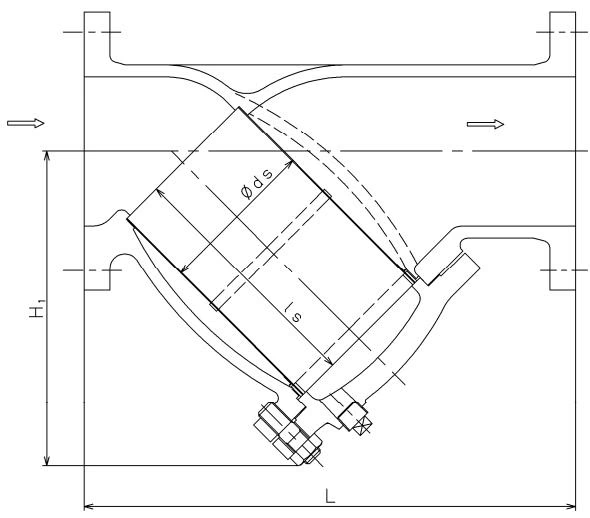 Figure 2: 65-300A
| Nominal size | L (mm) | H1 (mm) | ds (mm) | Ls (mm) | Connection | Weight (kg) |
|---|---|---|---|---|---|---|
| 15A | 130 | 61 | 22 | 40 | --- | 1.9 |
| 20A | 140 | 75 | 27 | 56 | --- | 2.5 |
| 25A | 160 | 88 | 34 | 66 | --- | 4.0 |
| 32A | 175 | 104 | 43 | 76 | --- | 5.2 |
| 40A | 190 | 115 | 50 | 85 | R 1/2 | 6.7 |
| 50A | 233 | 140 | 61 | 107 | R 1/2 | 10.2 |
| 65A | 290 | 167 | 73 | 125 | R 1/2 | 15 |
| 80A | 316 | 190 | 88 | 130 | R 1/2 | 19 |
| 100A | 360 | 225 | 108 | 180 | R 3/4 | 28 |
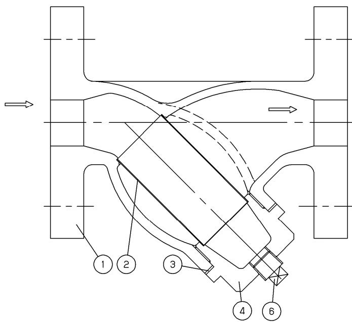 Figure 3: 15-50A
| No. | Part name |
|---|---|
| 1 | Body |
| 2 | Screen |
| 3 | Gasket |
| 4 | Cap |
| 5 | Cover |
| 6 | Plug |
| 7 | Strainer retainer |
| 8 | Hexagon nut |
| 9 | Stud bolt |
| 10 | Washer |
Dust, scale and other foreign matter from the fluid flowing into the strainer through the inlet port are removed by the screen.
WARNING
The product is heavy and shall be securely suspended with a hoist or the like when installed. Failure to suspend the product may cause it to fall down, possibly resulting in injury.
Installation Cautions
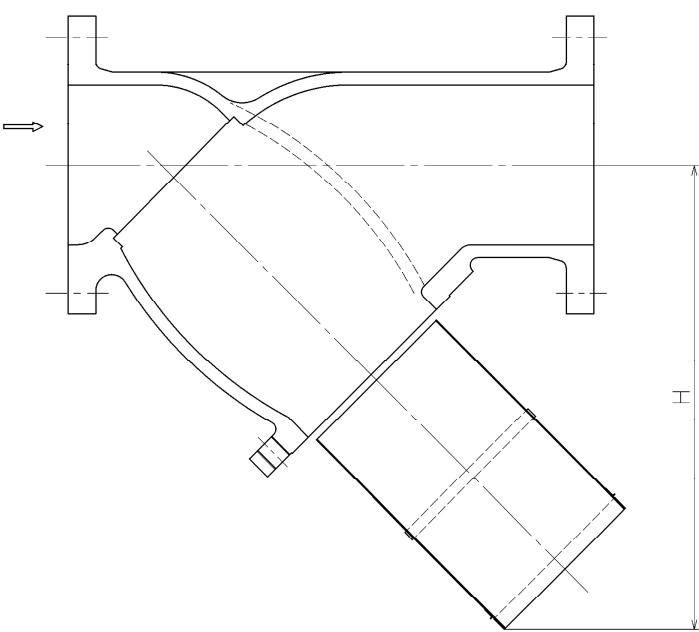 Figure 7: Space for removing the screen
| Nominal size | H (mm) |
|---|---|
| 15A | 80 |
| 20A | 105 |
| 25A | 125 |
| 32A | 145 |
| 40A | 160 |
| 50A | 200 |
| 65A | 220 |
| 80A | 245 |
| 100A | 310 |
WARNING
When overhauling or inspecting the product, check that the product and piping internal pressures have been released to the atmosphere. When the fluid is hot, cool it down until it can be touched by bare hand.
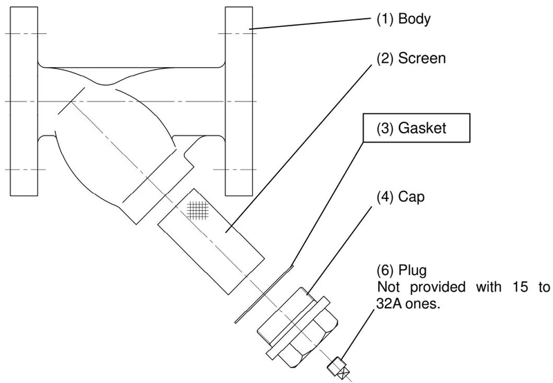 Figure 9: 15 to 50A
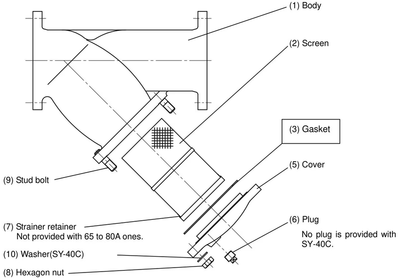 Figure 10: 65 to 300A
Yoshitake Instrumentation / Strainers
SY, SU, SW, and ST series strainers for removing line debris and protecting downstream valves and equipment.