3450 RPM Motors

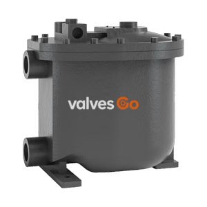
Yoshitake TFA-2000 float trap equipped with pump assist function for low pressure condensate in air-conditioning and heating units. Max 0.5 MPa.
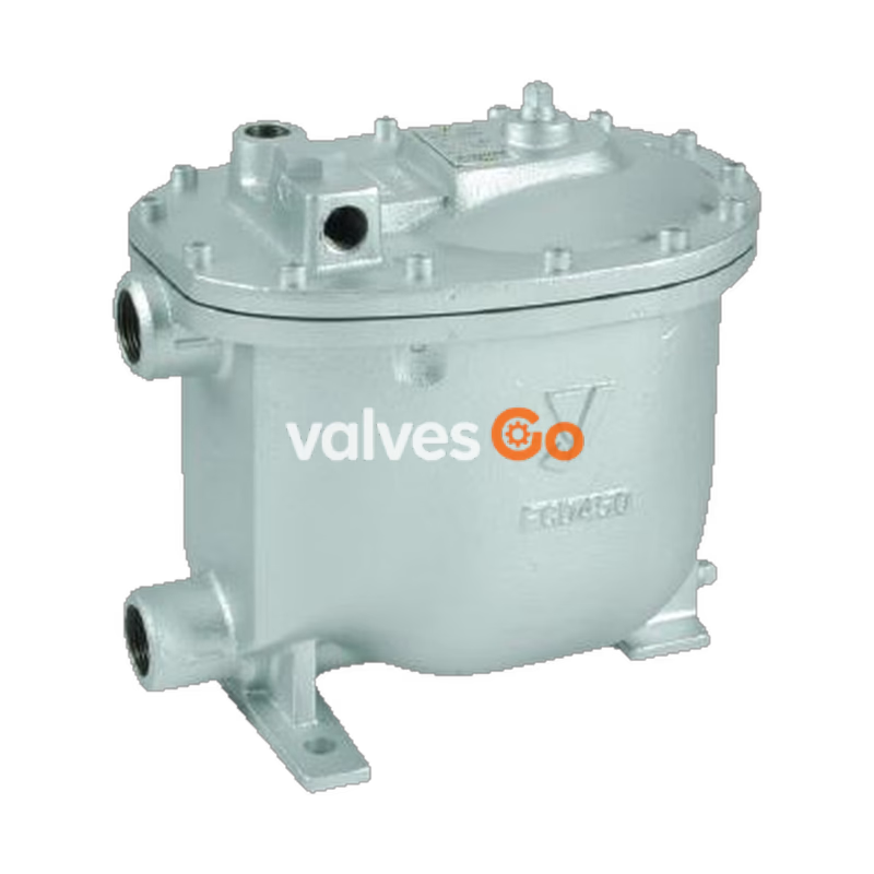
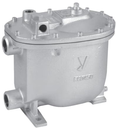
Yoshitake TFA-2000 is a float trap equipped with a pump assist function. It is most appropriate for the discharge of low-pressure condensate at air-conditioning units or heating units.
The intended purposes include:
| Specification | Value |
|---|---|
| Nominal size | 25A |
| Application | Steam condensate, Non-hazardous fluid |
| Motive fluid | Steam / Air |
| Max. working pressure | 0.5 MPa |
| Motive pressure | 0.03 to 0.5 MPa |
| Motive differential pressure | (Back pressure + 0.03 MPa) to 0.5 MPa |
| Max. working temperature | 160°C |
| Body Material | Ductile cast iron (FCD450) |
| Trim parts Material | Stainless steel |
| Float (P) Material | Stainless steel |
| Connection | JIS Rc screwed |
| Check valve at inlet side | Built-in (swing type) |
INFO
Install an optional check valve (SCV-2 or SCV-3) 25A on the outlet side of the product.
| Port | Connection |
|---|---|
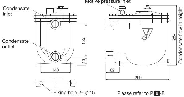
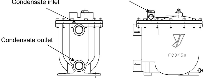
| Condensate inlet | Rc1 |
| Condensate outlet | Rc1 |
| Motive pressure inlet | Rc1/2 |
| Exhaust port | Rc1/2 |
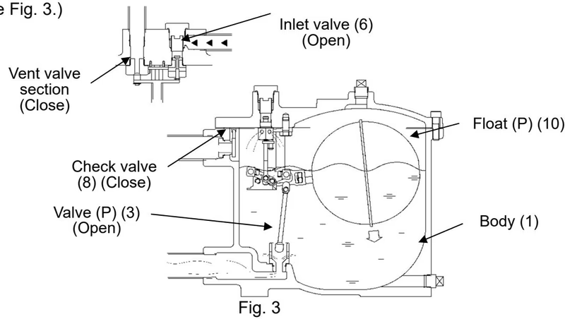
If the condensate flows from the condensate inlet through the check valve to the body, the float is moved up by the ascending force. In connection with the movement, the valve opens. If the pressure at the inlet side is larger than the back pressure on the product exit side, condensate is removed in this condition.
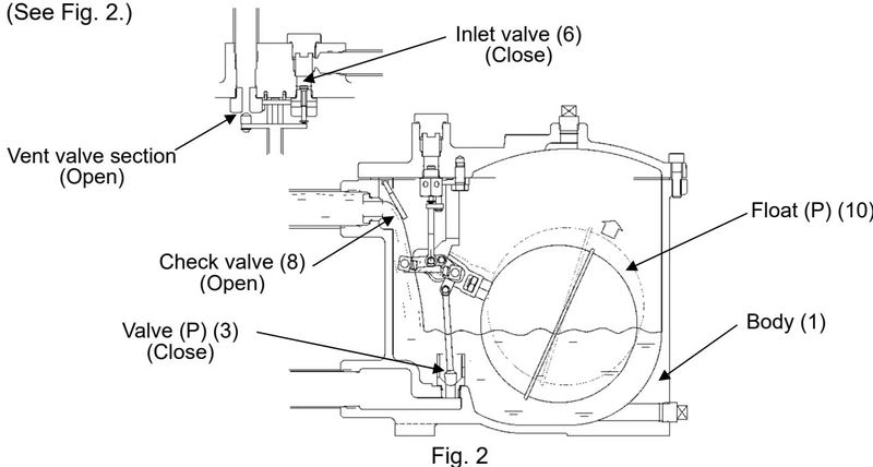
If the pressure at the inlet side is smaller than the back pressure at the product outlet side, condensate is accumulated in the body. When the condensate level ascends to the float level, the inlet valve opens and the vent valve section closes. The motive pressure is applied to the body and the check valve is closed. Condensate is fed to the outlet side and removed. After condensate is removed, the internal pressure is removed from the vent valve and the trap operation condition is recovered.
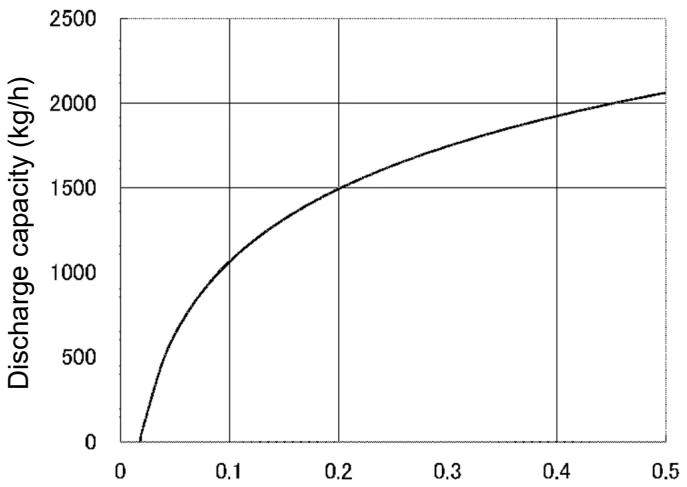
In trap operation, the discharge capacity depends on the difference between the condensate inlet pressure and back pressure (condensate outlet pressure). The safety rate shall be multiplied by 2 or 3 when selecting the capacity.
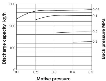
The assist capacity depends on the inflow height of condensate. Multiply the inflow height by the appropriate corrected coefficient shown in the table below.
Corrected Coefficient for Assist Capacity
| Inflow height (mm) | Corrected coefficient |
|---|---|
| 250 | 0.65 |
| 300 | 1.0 |
| 400 | 1.1 |
| 500 | 1.75 |
WARNING
Example of piping diagram (measures for condensate accumulation in air-conditioner)
INFO
There is a possibility that the inside of the heat exchanger becomes vacuum pressure by the usage condition.
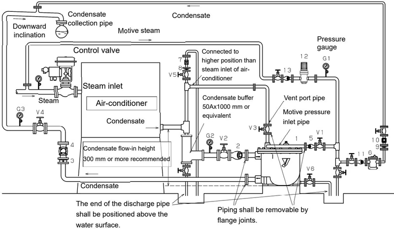
| No. | Name | No. | Name |
|---|---|---|---|
| 1 | Assist trap TFA-2000 25A | 2 | Strainer SY-40 25A (80 mesh) |
| 3 | Check valve SCV-3 25A | 4 | Sight glass SLM-1F 25A |
| 5 | Strainer SY-40 15A (80 mesh) | 6 | Steam trap TB-20F 15A |
| 7 | Air vent TS-5V 15A | 8 | Check valve SCV-3 15A |
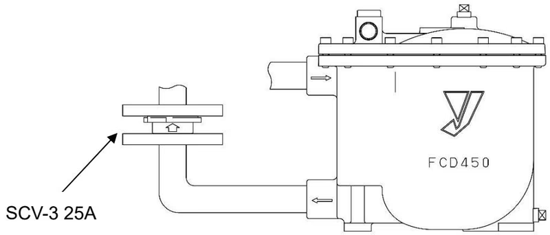
Attach the check valve (SCV-2 or SCV-3 25A) to keep the discharge capacity at the condensate outlet side. Note the direction of the check valve.
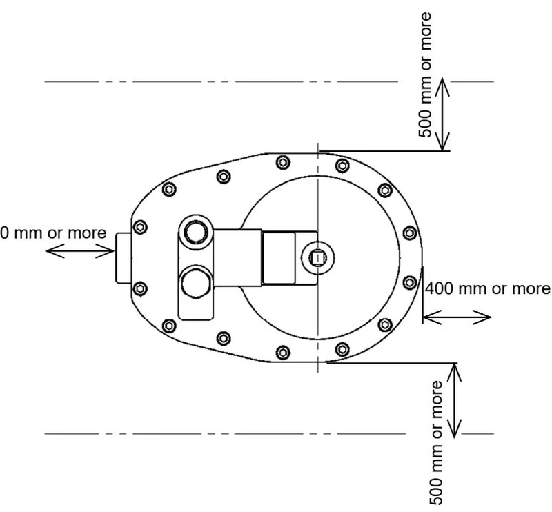
Provide the space for maintenance required for disassembling or correcting the product.
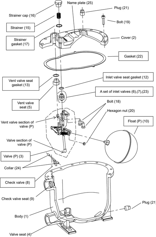
Periodic replacement parts
| Parts name | Recommended replacement timing |
|---|---|
| Valve (P) | Whichever earlier between 2 years and 100,000 times of switching operations |
| Float (P) | Whichever earlier between 2 years and 100,000 times of switching operations |
Yoshitake Pumps / Automatic Pump Traps
PF-7000 and TFA-2000 automatic pump trap series for condensate recovery under high back pressure.
Explore similar products in our catalog