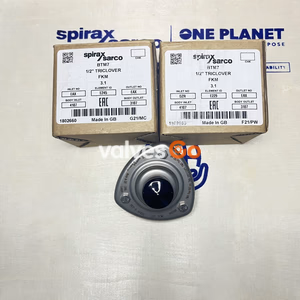
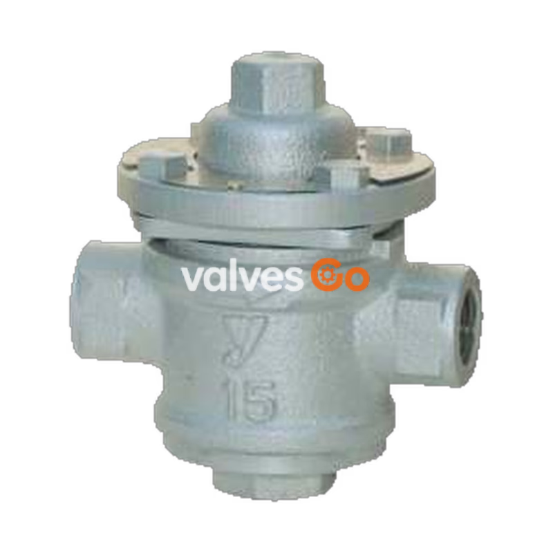
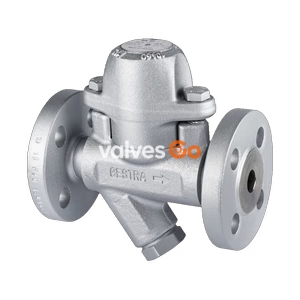
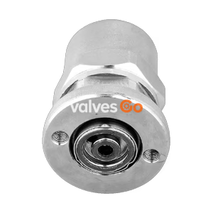
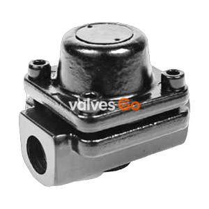
Yoshitake TS-7 is a thermostatic steam trap introducing welded bellows, designed for steam condensate applications. This model is equipped with an integrated bypass function that substantially reduces piping and installation costs. It operates at temperatures up to 12°C below saturation, preventing the discharge of live steam, and includes a built-in strainer.
Features
- Four functions (STOP / BY-PASS / TRAP / TEST) can be switched easily with a spanner or monkey wrench.
- The integrated bypass function helps reduce piping and construction work costs significantly.
- Applicable in a wide working pressure range due to welded bellows.
- Works at a 12°C lower temperature than the saturating temperature and discharges no live steam.
- Trap check can be performed without being affected by back pressure.
- The cock and valve, both made of stainless steel, are integrated into one unit.
- Equipped with a built-in strainer.
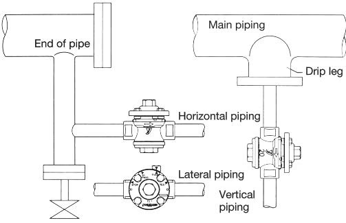
- Installable in any direction.
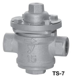
Specifications
| Specification | Value |
|---|
| Application | Steam condensate |
| Maximum Pressure | 1.0 MPa |
| Minimum Working Differential Pressure | 0.03 MPa |
| Maximum Temperature | 183°C |
| Body | Ductile cast iron |
| Cock (Valve seat) | Stainless steel |
| Bellows (Valve) | Stainless steel |
| Strainer | Stainless steel |
| Connection | JIS Rc screwed |
WARNING
When performing an airtightness test using water or air, keep the pressure at 0.5 MPa or less.
Dimensions and Weights
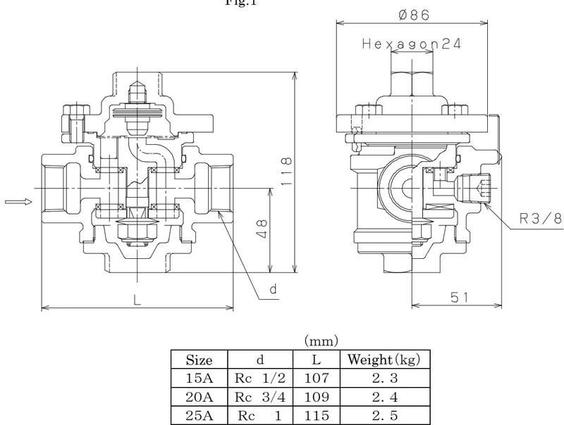
| Nominal size | d | L (mm) | Weight (kg) |
|---|
| 15A | Rc 1/2 | 107 | 2.3 |
| 20A | Rc 3/4 | 109 | 2.4 |
| 25A | Rc 1 | 115 | 2.5 |
(Note: The TS-8 model offers JIS 10K FF flanged connections with lengths from 156mm to 160mm and weights from 3.9kg to 5.5kg).
Discharge Capacity
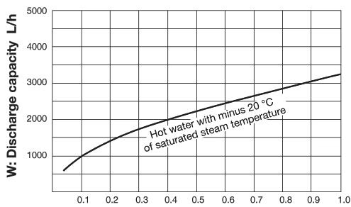
Maximum Continuous Discharge Capacity Table (L/h) (Hot water with minus 20°C of saturated steam temperature)
| Differential Pressure (MPa) | 0.03 | 0.05 | 0.1 | 0.2 | 0.3 | 0.4 | 0.5 | 0.6 | 0.7 | 0.8 | 0.9 | 1.0 |
|---|
| Discharge Capacity | 560 | 730 | 1020 | 1450 | 1780 | 2050 | 2300 | 2500 | 2700 | 2900 | 3100 | 3250 |
TIP
The discharge capacities shown are maximum values. In designing a system, select a steam trap with a sufficient safety factor (at least three times the regular level).
Switching Mechanism and Operation
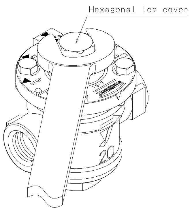
All steam traps are set at the "STOP" position when delivered. Functions can be switched by turning the hexagonal top cover using a monkey wrench to align the marker.
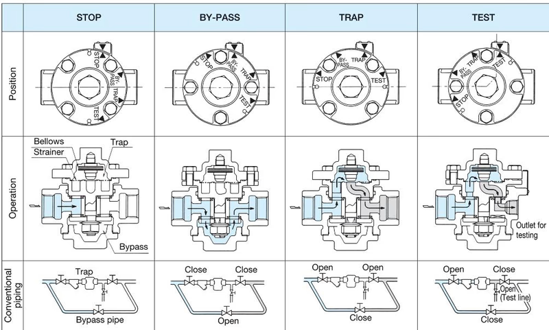
- STOP: Fluid does not flow into the trap and out of the bypass because the inlet, the outlet, and the bypass are closed. The strainer can be cleaned and the bellows can be inspected.
- BY-PASS: Fluid flows through the bypass directly to the outlet. Select this position when blowing the piping during plumbing or discharging a large quantity of condensate before starting operation. (Do not use at BY-PASS condition for a long time).
- TRAP: In this position, the steam trap performs regular trap operation, and condensate flows from the inlet to the outlet through the trap. It does not flow out of the bypass.
- TEST: Condensate is discharged from the inlet to the outlet for testing through the trap, and the operation of the trap can be checked without being affected by back pressure. Fluid does not flow out of the bypass.
Trap Mechanism
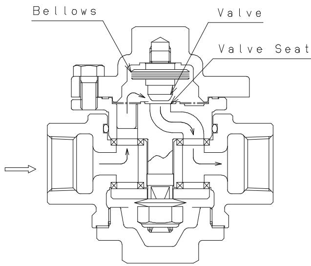
- When initially passing air: The bellows is contracted and the entire valve is fully opened. Discharge air and low temperature condensate swiftly.
- When closing the valve: When the condensate temperature has increased, sealing liquid inside the bellows evaporates, inner pressure increases, the bellows expands, and the valve is closed.
- When opening the valve: When the condensate has stopped flowing and the temperature has decreased, sealing liquid inside the bellows becomes condensed, inner pressure decreases, the bellows contracts, and the condensate is discharged.
Installation Procedures
- Carefully blow the piping before installing the steam trap.
- Connect the steam trap to the piping according to its arrow indicating the direction of flow.
- Slope the piping and place the product at as low a position as possible in order to make condensate flow into the product by its own weight.
- Do not insulate the piping inlet and the steam trap.
- To install the product in a main steam pipe, provide a drip leg at the inlet side of the product.
- Secure enough space for switching operation of the cock and maintenance (such as cleaning the strainer and inspection of the bellows).
- If discharge capacity is not enough, install more than one trap. In this case, connect the traps to the piping so that their inlets are in the same level.
- Do not install the steam trap in a place where ambient temperature is higher than the condensate to be discharged.
WARNING
- Do not use sudden opening and closing valves in front and behind the trap to prevent water hammer, which can damage the bellows.
- Avoid using the equipment with frequent repetition of ventilation and steam stop via electromagnetic valves.
Maintenance
- Condensate is not discharged: Check if the cock is set to STOP. If bellows is damaged, replace the cover complete set.
- Condensate cannot be discharged smoothly: The strainer might be clogged. Disassemble and clean it. Or the differential pressure is insufficient due to high back pressure.
- Steam leaks: Ensure the cock is not set to BY-PASS. Check for foreign matter or abraded valve/seat.
INFO
Daily and periodic inspections are necessary to keep the product's function and performance. Disassembly and inspection should ideally be left to specialists.