


PN16

The Yoshitake TSF-11 is a float steam trap with an incorporated thermostatic air vent for steam condensate. Features ductile cast iron body, max pressure of 2.1 MPa, and operates up to 220°C.
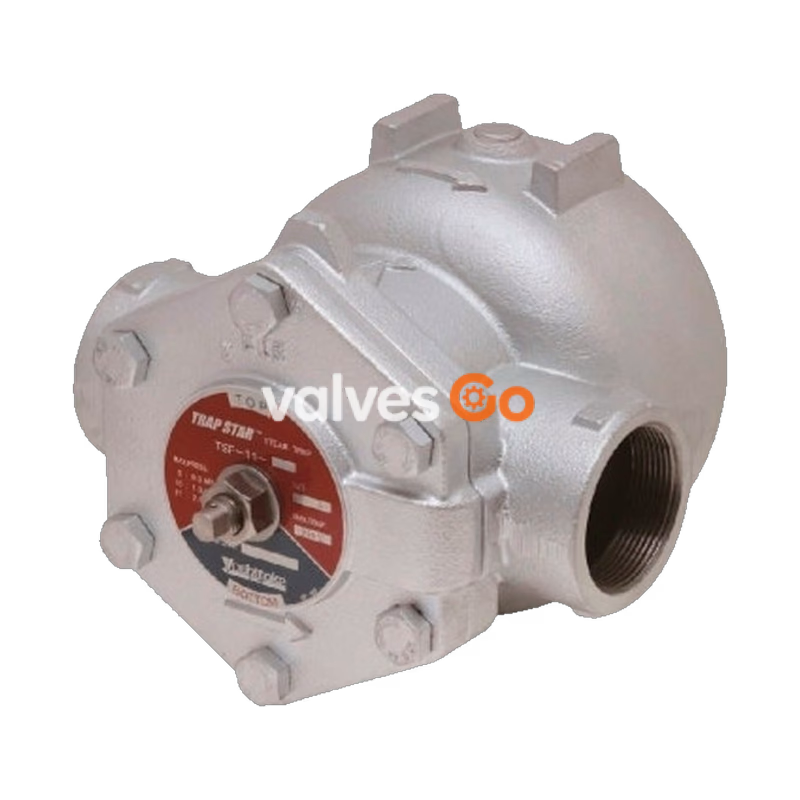
The Yoshitake TSF-11 is a float-type steam trap equipped with an incorporated thermostatic air vent. It is designed to discharge steam condensate effectively without retention, realizing an energy-saving steam system without steam loss. The incorporated thermostatic air vent discharges air inside the piping and significantly shortens warming-up time.
By turning the cock, the flow direction can be switched easily to accommodate horizontal or vertical installations without disassembling the cover. Since all main parts are installed on the cover, inspection and parts replacement can be conducted easily with the body remaining installed on the piping.
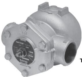
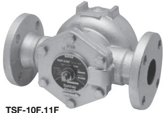
| Model | TSF-11 | TSF-11F |
|---|---|---|
| Nominal size | 25A - 50A | 25A - 50A |
| Application | Steam condensate | Steam condensate |
| Working pressure | TSF-11-5: 0.01-0.5 MPa TSF-11-10: 0.01-1.0 MPa TSF-11-21: 0.01-2.1 MPa | TSF-11F-5: 0.01-0.5 MPa TSF-11F-10: 0.01-1.0 MPa TSF-11F-21: 0.01-2.1 MPa |
| Maximum temperature | 220°C | 220°C |
| Body material | Ductile cast iron | Ductile cast iron |
| Float material | Stainless steel | Stainless steel |
| Valve & seat material | Stainless steel | Stainless steel |
| Connection | JIS Rc screwed, NPT screwed | JIS 10K FF, JIS 20K FF flanged, ASME150/300, ENPN25 |
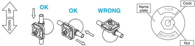
Adjust the direction of the nameplate in a no-pressure condition after installation.
Fix the cock with a spanner and loosen the nut. Turn the cock and adjust the direction of the nameplate to position the "TOP" and "BOTTOM" signs upside and downside respectively. Fix the cock with a spanner and fasten the nut after adjustment.
WARNING
In case of a bottom-to-top flow, please shorten the vertical piping before the trap to allow it to open and discharge easily when using an upward flow direction.
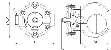
| Nominal size | d | L (mm) | A (mm) | A1 (mm) | H (mm) | Weight (kg) |
|---|---|---|---|---|---|---|
| 25A | Rc 1 | 190 | 244 | 147 | 186 | 9.9 |
| 32A | Rc 1-1/4 | 190 | 244 | 147 | 186 | 10.0 |
| 40A | Rc 1-1/2 | 205 | 244 | 147 | 186 | 10.2 |
| 50A | Rc 2 | 220 | 244 | 147 | 186 | 10.5 |
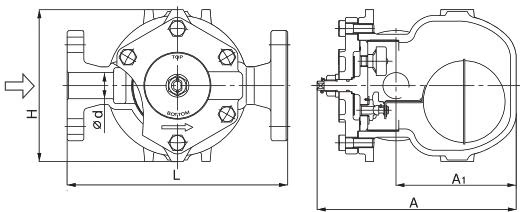
| Nominal size | d (mm) | L (mm) | A (mm) | A1 (mm) | H (mm) | Weight (kg) |
|---|---|---|---|---|---|---|
| 25A | 25 | 270 | 244 | 147 | 186 | 13.4 |
| 32A | 32 | 270 | 244 | 147 | 186 | 14.1 |
| 40A | 40 | 280 | 244 | 147 | 186 | 14.4 |
| 50A | 50 | 290 | 244 | 147 | 186 | 15.5 |
TIP
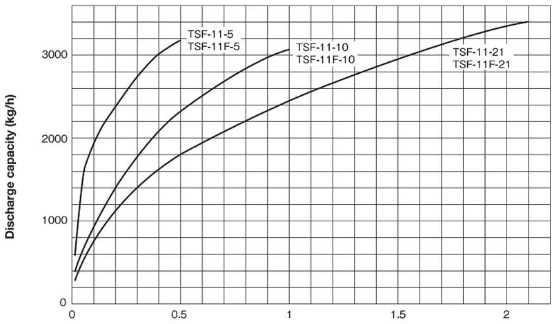
The discharge capacity shown in the chart above is the maximum value. When designing a system, select a steam trap with a sufficient safety factor (more than two times the regular level).
Yoshitake Steam Traps / Float Steam Traps
TF and TSF series float steam traps for continuous condensate drainage in steam systems.





