Lift Type
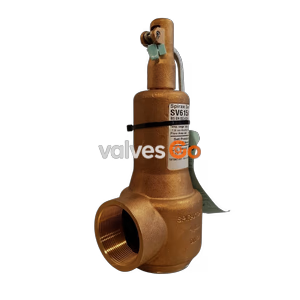
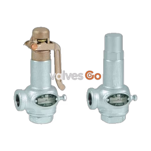
Yoshitake VB-7 and VB-7S vacuum relief valves. Protects devices and piping by adjusting vacuum pressure. Available in brass (VB-7) or stainless steel (VB-7S) for steam and air, up to 200°C.
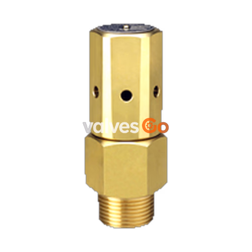
The Yoshitake VB-7 and VB-7S are vacuum relief valves designed to protect devices and piping by adjusting vacuum and preventing accidents resulting from vacuum pressure. The VB-7 is constructed with a brass body and bronze valve, while the VB-7S is made of stainless steel for improved corrosion resistance. Both models feature a special valve structure that ensures stable performance without chattering and hunting, in a compact, lightweight design that is easy to handle.
Seat Leakage and Vibration
| Model | VB-7 | VB-7S |
|---|---|---|
| Application | Steam, Air | Steam, Air |
| Working Pressure | 1.0 MPa | 1.0 MPa |
| Pressure Regulating Range (Spring A) | -0.5 to -21 kPa (Standard set: -4 kPa) | -0.5 to -21 kPa (Standard set: -4 kPa) |
| Pressure Regulating Range (Spring B) | -21 to -48 kPa (Standard set: -21 kPa) | -21 to -48 kPa (Standard set: -21 kPa) |
| Pressure Regulating Range (Spring C) | -48 to -81 kPa (Standard set: -48 kPa) | -48 to -81 kPa (Standard set: -48 kPa) |
| Maximum Temperature | 200°C | 200°C |
| Body Material | Brass | Stainless steel |
| Valve Material | Bronze | Stainless steel |
| Valve Seat Material | Brass | Stainless steel |
| Connection | JIS Rc screwed | JIS Rc screwed |
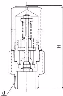
| Nominal Size | d | H (mm) | A (mm) | Weight (kg) |
|---|---|---|---|---|
| 15A | Rc 1/2 | 100.0 | 35 | 0.50 |
| 20A | Rc 3/4 | 100.0 | 35 | 0.50 |
| 25A | Rc 1 | 112.5 | 41 | 0.75 |
| 32A | Rc 1-1/4 | 113.5 | 50 | 1.05 |
| 40A | Rc 1-1/2 | 130.0 | 55 | 1.45 |
| 50A | Rc 2 | 156.5 | 65 | 2.45 |
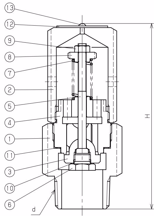
| No. | Name of Parts | Material (VB-7) |
|---|---|---|
| 1 | Body | Brass (C3604) |
| 2 | Cap | Brass (C3604) |
| 3 | Valve | Bronze (CAC406) |
| 4 | Valve Seat | Brass (C3604) |
| 5 | Spindle | Brass (C3604) |
| 6 | Plug | Brass (C3604) |
| 7 | Spring | Stainless Steel (SUS304) |
| 8 | Adjusting Screw | Brass (C3604) |
| 9 | Lock Nut | Brass (C3604) |
| 10 | Gasket | Copper (C1100) |
| 11 | Gasket | Copper (C1100) |
| 12 | Name Plate | Stainless Steel (SUS304) |
| 13 | Rivet | Carbon Steel (S15C) |
When the negative pressure in the equipment or piping increases and approaches the set pressure (suction pressure), the force of the fluid opening valve (3) balances with the force of the adjusting spring (7) closing valve (3), and slight pre-leakage occurs. If the negative pressure increases further, valve (3) will open. The degree of opening of valve (3) changes according to the variation of negative pressure in the equipment and piping, thereby controlling the amount of induced air and maintaining a predetermined vacuum level.
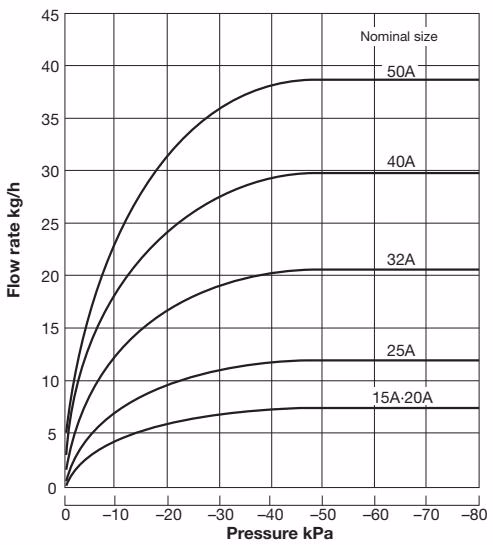
Note: The flow rate in the chart above is for reference only.
Example piping for temperature control equipment
Example piping for silencer without check valve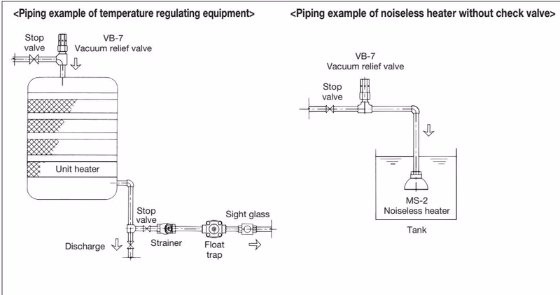
Installation Precautions
| Symptoms | Causes | Countermeasures |
|---|---|---|
| Leakage confirmed visually from the cap or by sound | 1. Foreign matter/scale caught between the contact surfaces of the valve (3) and valve seat (4). 2. Scratches on the contact surfaces of the valve and seat. 3. Product malfunction caused by excessive vibration from connected piping. 4. The difference between the set pressure and the normal working pressure is too small. 5. Unsmooth operation of the sliding parts of the valve and seat. | 1. Repair at the factory is required. 2. Disassembly and part replacement are required (repair at factory). 3. Do not use this product in equipment or devices with excessive vibration. 4. Increase the difference between the set pressure and normal working pressure. (Readjustment requires factory repair). 5. Disassembly and cleaning are required (repair at factory). |
| Operates below the set pressure | 1. Product specifications and operating conditions are incompatible. 2. Pressure gauge malfunction. 3. Deviation in product pressure setting. | 1. Check the pressure setting value on the nameplate (12). Change the product if operating conditions differ. 2. Calibrate or replace the pressure gauge. 3. Repair at the factory is required. |
| Does not operate when set pressure is reached | 1. Product specifications and operating conditions are incompatible. 2. Pressure gauge malfunction. 3. Deviation in product pressure setting. 4. Unsmooth operation of sliding parts. | 1. Check the pressure setting value on the nameplate (12). Change the product if operating conditions differ. 2. Calibrate or replace the pressure gauge. 3. Repair at the factory is required. 4. Disassembly and cleaning are required (repair at factory). |
INFO
The seat leakage of this product is within the allowable range and cannot be completely closed (zero seat leakage).