


PN16

Armstrong FF-4000 Series float and thermostatic steam trap with 360° universal connector. Features all-stainless steel construction, compact design, and bimetal air vent.
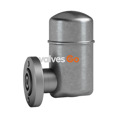
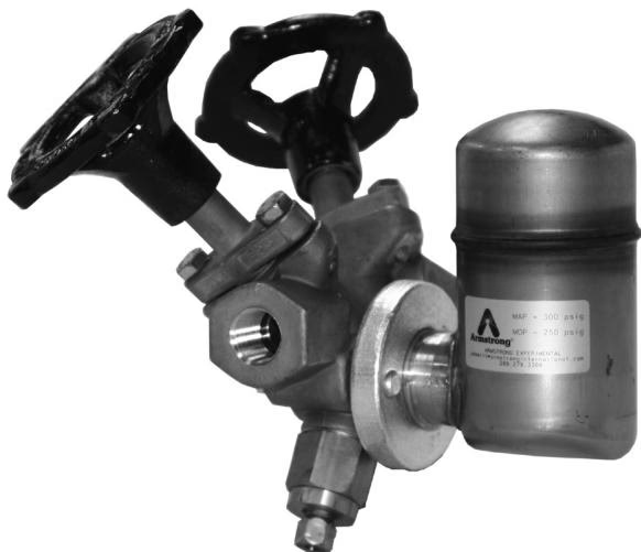
Armstrong FF-4000 Series float and thermostatic steam traps combine savings in three important areas: energy, installation, and replacement. With the FF-4000 Series' 360° universal connector, you can install the float and thermostatic trap in a vertical position to fit any piping configuration. You get the reliability of the freely floating ball and thermostatic design plus all the benefits of all-stainless steel construction. Mounting the FF-4000 on universal connectors provides quick and easy in-line replacement.
The FF-4000 Series features a sealed, tamperproof package, a compact and lightweight design, and exceptional corrosion resistance.
Maximum allowable pressure (vessel design):
Maximum operating pressure:
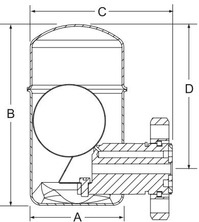
| Model No. | FF-4250 | FF-4250 | FF-4450 | FF-4450 |
|---|---|---|---|---|
| Pipe Connection | 1/2, 3/4 in | 15, 20 mm | 1/2, 3/4 in | 15, 20 mm |
| “A” Diameter | 2-11/16 in | 68 mm | 3-7/8 in | 98 mm |
| “B” Height | 4-7/8 in | 124 mm | 6-3/16 in | 157 mm |
| “C” Outside to Flange”D” | 3-7/8 in | 98 mm | 4-15/16 in | 125 mm |
| “D” C Flange to Top | 4 in | 102 mm | 4-15/16 in | 125 mm |
| Trap Only Weight | 2 lb | 0.9 kg | 4 lb | 1.8 kg |
Before installation, verify that the maximum allowable pressure/temperature and maximum operating pressure of the trap are sufficient to handle the system design pressure and temperature. This information can be found on the label located on the trap. Steam trap installation is critical from both a performance and maintenance aspect. Installation of the trap is simplified if you follow these guidelines.
WARNING
Due to the high temperatures of steam, trap surface will be hot. For personal safety, ensure proper precaution is taken while working near the steam trap.
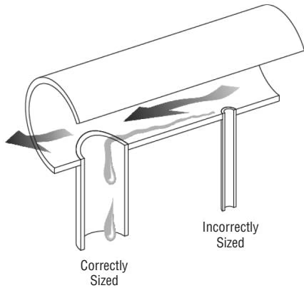
Drip Leg Length Minimum
| Steam Main Size | Drip Leg Diameter | Supervised Warm-Up | Automatic Warm-Up |
|---|---|---|---|
| 1/2 in (13 mm) | 1/2 in (13 mm) | 10 in (254 mm) | 28 in (711 mm) |
| 3/4 in (19 mm) | 3/4 in (19 mm) | 10 in (254 mm) | 28 in (711 mm) |
| 1 in (25 mm) | 1 in (25 mm) | 10 in (254 mm) | 28 in (711 mm) |
| 2 in (51 mm) | 2 in (51 mm) | 10 in (254 mm) | 28 in (711 mm) |
| 3 in (76 mm) | 3 in (76 mm) | 10 in (254 mm) | 28 in (711 mm) |
| 4 in (102 mm) | 4 in (102 mm) | 10 in (254 mm) | 28 in (711 mm) |
| 6 in (152 mm) | 4 in (102 mm) | 10 in (254 mm) | 28 in (711 mm) |
| 8 in (203 mm) | 4 in (102 mm) | 12 in (305 mm) | 28 in (711 mm) |
| 10 in (254 mm) | 6 in (152 mm) | 15 in (381 mm) | 28 in (711 mm) |
| 12 in (305 mm) | 6 in (152 mm) | 18 in (457 mm) | 28 in (711 mm) |
| 14 in (356 mm) | 8 in (203 mm) | 21 in (533 mm) | 28 in (711 mm) |
| 16 in (406 mm) | 8 in (203 mm) | 24 in (607 mm) | 28 in (711 mm) |
| 18 in (457 mm) | 10 in (254 mm) | 27 in (686 mm) | 28 in (711 mm) |
| 20 in (508 mm) | 10 in (254 mm) | 30 in (762 mm) | 30 in (762 mm) |
| 24 in (610 mm) | 12 in (305 mm) | 36 in (914 mm) | 36 in (914 mm) |
Note: Drip leg same as the header diameter up to 4’’ (102 mm). Above 4’’ (102 mm), 1/2 header size, but never less than 4’’ (102 mm).
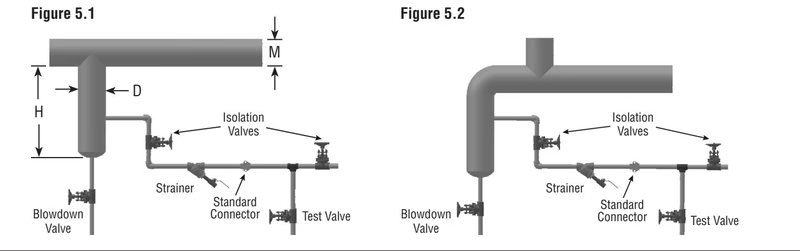
The Standard connector block should be installed in piping with the flow direction stamp pointing in the correct direction as indicated on the connector block.
TIP
Armstrong strongly recommends adding an upstream strainer before the trap and isolation valves upstream and downstream of the trap.
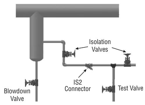
The IS2 connector block should be installed in piping with the flow direction stamp pointing in the correct direction as indicated on the connector block.
TIP
Armstrong strongly recommends isolation valves upstream and downstream of the trap.
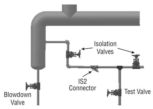
The TVS-4000/TVS-4000F connector block should be installed in piping with the flow direction stamp pointing in the correct direction as indicated on the connector block.
Note: The TVS-4000 has integral strainer and isolation valves.
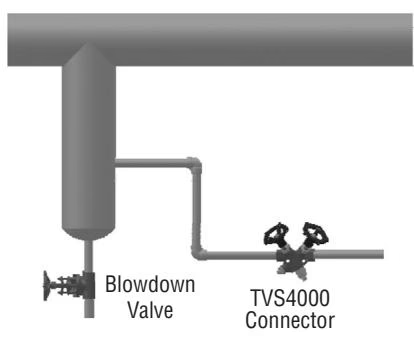
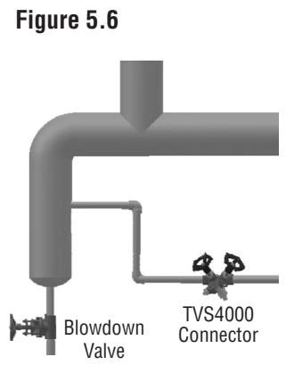
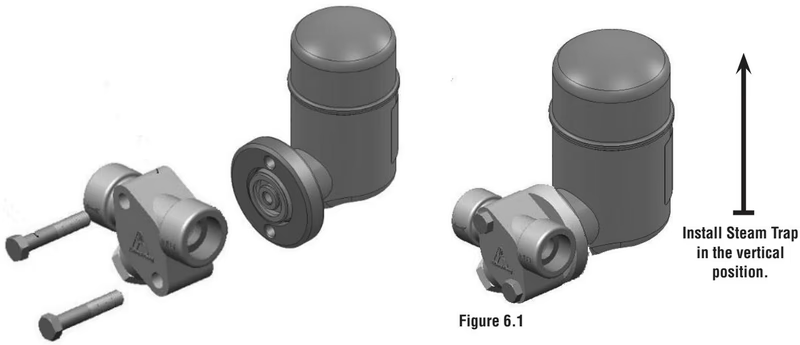
Important: Even though the connector block can be installed in any direction, FF-4000 Series steam traps need to be installed in the vertical position (up right). The flange of the steam trap rotates 360 degrees to allow the trap to be installed this way regardless of the installation of the connector block.
When the steam trap is suspected of malfunctioning, it can be checked by observing the discharge of the trap. Normal trap operation would be indicated by:
All discharges are accompanied by large amounts of flash steam. Do not confuse the discharge of flash steam with live steam loss. If the trap blows live steam, isolate the trap and replace.
Whenever a steam trap fails to operate and the reason is not readily apparent, the discharge from the trap should be observed. If the trap is installed with a test outlet or discharges to atmosphere, this will be a simple matter - otherwise, it will be necessary to break the discharge connection.
1. Cold Trap - No Discharge No condensate or steam coming to trap.
2. Steam Loss If the trap leaks or blows live steam, trouble may be due to any of the following causes:
Imaginary Troubles: If it appears that steam escapes every time trap discharges, remember: Hot condensate forms flash steam when released to lower pressure, but usually condenses quickly in the return line.
If the trap is found defective:
FF-4000 Series is a sealed trap and is non-repairable. If the trap fails, a new one will need to be installed.




