

PN16

BURKERT 20017437 (Type 8640) 16-bank modular pneumatic valve block provides 3/2-way valve functions, G 1/2 pressure ports, G 1/4 working ports, 2 to 8 bar nominal pressure, single wiring, and DIN-rail mounting.
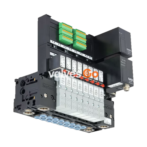
BURKERT 20017437 (Type 8640) is a 16-bank modular pneumatic valve block configured for 3/2-way valve functions. Built with an add-on station spacing dimension of 33 mm, the assembly incorporates G 1/2 process connections on the primary pressure supply side and G 1/4 pneumatic working ports arranged opposite the supply side. Operating across a nominal pressure range of 2.00 bar to 8.00 bar, the unit handles neutral gases and filtered, compressed dry air between 0 °C and +50 °C.
Designed for integration directly into control cabinets or distribution panels, the unit utilizes single wiring for electrical actuation without an internal bus interface, achieving an ingress protection rating of IP20. Mechanical stabilization is established through integrated DIN-rail clamping compatible with standard EN 50022 mounting rails. The valve block body and intermediate pneumatic segments are fabricated from polyamide, joined via snap-in mechanical connectors to form a rigid pneumatic manifold assembly.

| Specification Parameter | Value / Execution |
|---|---|
| Product Model / Identifier | Type 8640 / Article No. 20017437 |
| Total Number of Valve Stations | 16-bank (16 valve positions) |
| Valve Circuit Function | 3/2-way valve function |
| Station Add-on Dimension | 33 mm |
| Pressure Port 1 (P) | G 1/2 female thread |
| Working Ports 2 (A) | G 1/4 female thread |
| Working Connection Position | Opposite of supply side |
| Nominal Operating Pressure Range | 2.00 bar to 8.00 bar |
| Medium Operating Temperature Range | 0.00 °C to +50.00 °C |
| Permissible Ambient Temperature Range | 0.00 °C to +55.00 °C |
| Permissible Storage Temperature | -20.00 °C to +60.00 °C (-40 °C to +55 °C packaged) |
| Operating Medium | Oil-free or lubricated compressed dry air, neutral gases |
| Compressed Air Quality Standard | ISO 8573-1:2010, Class 7.4.4 (5 µm filtration recommended) |
| Electrical Interface | Single wiring (individual parallel stranded connections) |
| Internal Bus Communication | Without (due to single wiring execution) |
| Digital Inputs (EME Module) | 0 PCE |
| Nominal Operating Mode | 100% continuous duty cycle (ED) |
| Protection Class | III according to VDE 0580 |
| Ingress Protection Rating | IP20 (with appropriate connectors fitted) |
| Mounting Standard | DIN-rail mounting according to EN 50022 (35 x 7.5 or 35 x 15 mm) |
| Manual / Automatic Switching | No |
| Pneumatic HotSwap at Port 1 (P) | No |
| Integrated Check Valves in Port 3 (R) / 5 (S) | No |
| Intermediate Supply Ports | 0 PCE |
The 16-station block configuration routes high-flow pneumatic pilot air through common supply channels within modular polyamide base segments. The central supply port 1 (P) is sized at G 1/2, ensuring uniform volume delivery across all 16 valve banks without requiring intermediate feed plates. Working ports 2 (A) are tapped at G 1/4 and situated on the manifold side opposite the main supply connection to simplify direct panel routing.
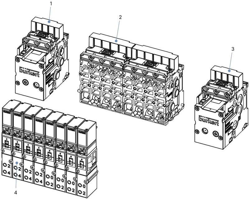
Pneumatic module assemblies rely on internal elastomeric sealing profiles to isolate flow chambers between adjacent manifold segments. Compressed air feeding the island must fulfill ISO 8573-1:2010 Class 7.4.4, with filtration recommended to 5 µm or finer to prevent seat contamination.
Single Wiring Execution
Article 20017437 is built specifically for discrete electrical wiring. It does not contain an internal serial bus, gateway interface, or fieldbus coupling module. Solenoids are addressed and switched independently via discrete lines.
Article 20017437 uses discrete point-to-point connections where each solenoid station receives independent power and signal lines. The operating voltage is 24 V DC (±10% allowable voltage tolerance, with maximum residual ripple of 1 Vss). Under continuous duty cycle, the coil design maintains stable thermal characteristics when supplied with rated DC power.
Each valve slot features a mechanical manual override mechanism on the pilot valve assembly. To operate the valve manually during dry-cycling or testing, press down the manual override element and rotate it 90° clockwise until it latches. The mechanism remains locked in the active position until manually rotated counter-clockwise back to the neutral zero position.
Operational Restriction
Operate the mechanical manual override only when the electrical supply voltage is disconnected. Unlocking the override back to zero position is strictly required prior to restoring normal automated electrical operation.
Manifold bodies are manufactured from injection-molded polyamide (PA), interconnected using interlocking snap-in hooks and matching retaining tabs. The base segments hold the valve modules in alignment while providing rigid anchoring points for DIN-rail attachment.
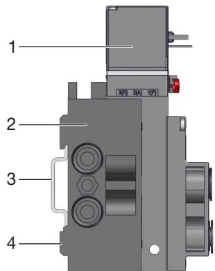
When connecting rigid fittings or pneumatic push-in adapters to the female threaded ports, follow standard torque limits to prevent stress cracking in polyamide manifold blocks:
Piping Installation Precaution
Never use the solenoid coil or pilot body as a lever arm when tightening threaded process fittings. Seal male threads using PTFE tape or appropriate elastomeric sealing rings without introducing pipe wrench stress to the plastic module housing.
Before charging the assembly with compressed air, inspect all line connections, verify that supply lines are blown clear of metal shavings or dust, and confirm that manual overrides are disengaged.
| Fault Condition | Probable Cause | Corrective Action |
|---|---|---|
| Valves fail to actuate | Insufficient or absent operating voltage | Verify wiring connections; confirm 24 V DC ±10% on active terminals. |
| Valves fail to actuate | Manual override locked in actuated position | Disengage mechanical lock; return override slot to zero position. |
| Valves fail to actuate | Supply pressure below 2.00 bar threshold | Increase upstream air pressure; inspect upstream regulators and filter bowls. |
| Delayed switching or continuous venting at exhaust | Back-pressure build-up from restricted exhaust or clogged silencers | Clean or replace exhaust silencers; inspect exhaust line dimensions. |
| Delayed switching | Solenoid energized prior to system pressure build-up | Establish pneumatic manifold pressure before applying electrical control signals. |
| Manifold block leakage | Crushed or missing inter-module O-rings | Disassemble module latching hooks; replace damaged sealing rings and apply grease. |
| Manifold block leakage | Valve seating seal misaligned | Check flat valve base gasket; re-tighten mounting screws to 0.6 ±0.1 Nm. |
Explore similar products in our catalog


