

PN16

BURKERT 20042555 (Type 8647) is an 8-slot AirLINE SP pneumatic valve island with AirLINE Quick REV.2 stainless steel base, G 1/4 ports, D6 push-in connections, P hot swap, and Siemens ET 200SP integration.
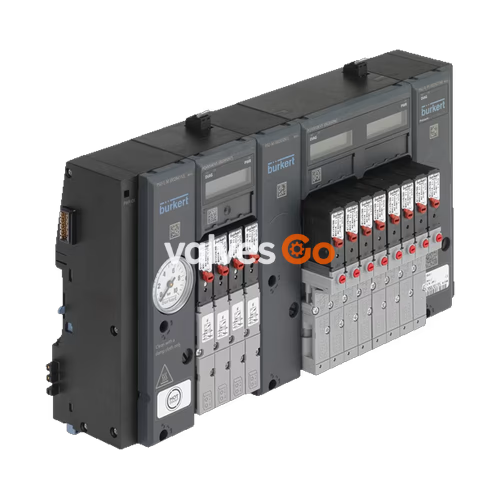
BURKERT 20042555 Type 8647 AirLINE SP is an 8-slot electro-pneumatic valve island engineered for direct integration into the Siemens SIMATIC ET 200SP distributed I/O system. Built in an 11 mm width-per-station configuration with Revision 2 (REV.2) architecture, the unit features an AirLINE Quick stainless steel cabinet floor mounting plate, mixed valve population flexibility, bottom-facing D6 push-in working connections, and G 1/4 supply and exhaust ports. It operates within a nominal pressure span of 2.5 bar to 10.0 bar and an ambient operating temperature range of 0 °C to +55 °C.
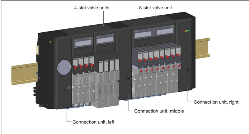
Equipped with integrated pneumatic HotSwap functionality in supply channel 1 (P) and integrated check valves in exhaust channels 3 (R) and 5 (S), the assembly permits valve replacement under live operating pressure while preventing exhaust back pressures from triggering unintended actuator switching. The assembly carries an IP20 device rating and achieves UL Type 4X and IP65 protection in closed control cabinets via the AirLINE Quick interface.
Type 8647 AirLINE SP connects directly to the backplane bus and power bus of the Siemens SIMATIC ET 200SP automation system without intermediate wiring. Electrical load voltage (24 V DC ±10% SELV/PELV) and internal communication are supplied through adjacent SIMATIC ET 200SP BaseUnits. Configuration occurs in Siemens TIA Portal (version 13 or higher), STEP 7 Classic (version 5.5 SP4 or higher), or third-party engineering environments via GSDML and HSP.
AirLINE Quick System Compatibility
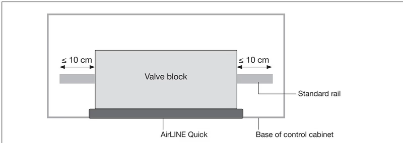
AirLINE Quick control cabinet base adaptation cannot be combined with SIMATIC ET 200SP HA due to mechanical enclosure constraints. For ET 200SP installations, standard DIN rail projection must not exceed 10 cm on either side of the valve block, and only short BaseUnits may be used.
Article 20042555 incorporates Bürkert Revision 2 (REV.2) pneumatic components. In REV.2, fluidic interfaces between single valves, double valves, and the pneumatic base modules are standardized under the FM20 flange profile.
| Distinguishing Feature | Revision 1 (REV.1) | Revision 2 (REV.2 - 20042555) |
|---|---|---|
| Release Ring Color | Black | Blue |
| Working Port Channel Geometry | Parallel linear alignment | Wavy offset alignment |
| Type Label Revision Marking | Unmarked (no Rev. text) | Marked with "Rev.2" |
| Valve Flange Interface | Dissimilar (FM14 single / FM20 double) | Unified FM20 flange standard |
| HotSwap Flow Reduction | Up to 50% flow reduction | Approximately 20% flow reduction |
Single Valve Mechanical Interchangeability
Single pilot valves from REV.1 and REV.2 are not mechanically interchangeable on the pneumatic sub-base due to differing port cross-sections and flange geometries. Replace REV.2 valve slots only with REV.2 designated spare valves.
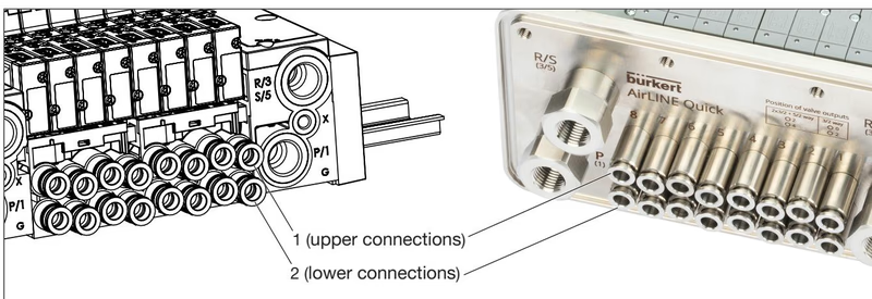
AirLINE Quick allows bottom mounting of the valve block directly into a cutout on the floor of the control cabinet. The stainless steel adapter plate seals the enclosure, and all pneumatic working lines (D6) route downward outside the cabinet interior. This layout physically separates electronic I/O hardware from pneumatic piping.
Connection units handle bulk media supply and deaeration, while individual pneumatic base modules route air to the actuators through bottom-oriented D6 push-in connectors.
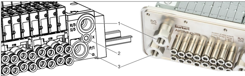
| Port Identification | Marking | Port Size / Type | Functional Assignment |
|---|---|---|---|
| Port 1 | P/1 | G 1/4 | Compressed air supply (2.5 to 10.0 bar) |
| Port 3 / 5 | R/3, S/5 | G 1/4 | Exhaust air deaeration channels |
| Port X | X | M5 | Auxiliary pilot air or pilot exhaust |
| Working Ports | 2, 4 | D6 Push-in | Actuator supply (bottom pneumatic base) |
HotSwap and Exhaust Back Pressure Protection
Pneumatic HotSwap enables individual pilot valves to be loosened and replaced while supply line 1 (P) remains pressurized. An automatic shutoff valve closes the P gallery at the valve seat, allowing brief localized exhaust before sealing. Integrated check valves in ports 3 and 5 prevent pressure pulses in common exhaust lines from back-feeding into inactive pneumatic actuators.
| Connection Thread | Function | Recommended Torque | Maximum Torque |
|---|---|---|---|
| G 1/4 | P supply, R/S exhaust | 4.0 Nm to 7.0 Nm | 20.0 Nm |
| M5 | Auxiliary pilot air (X) | 1.0 Nm to 1.2 Nm | 3.0 Nm |
| M7 | Push-in cartridge fitting | 1.75 Nm to 2.25 Nm | 4.0 Nm |
| M5x10 | AirLINE Quick stability plate | 2.0 Nm | 2.0 Nm |
Type 8647 receives control commands via the backplane bus and draws coil power from the 24 V DC power bus. A light-colored BaseUnit (BU...D or BU...D/T) placed directly to the left splits the load voltage potential group.
Push-in connections comply with ISO 14743:2020. Tubing cuts must be straight (90°) and free of burrs or scratches to ensure airtight clamping.
| Tubing Material | Outside Diameter (OD) | Permissible OD Deviation | Minimum Tensile Holding Force |
|---|---|---|---|
| Polyamide (PA) | 6.0 mm (D6) | ±0.08 mm | 120 N |
| Polyurethane (PU) | 6.0 mm (D6) | ±0.10 mm | 100 N |
For flexible polyurethane (PU) tubing operating at elevated pressures or vibrations, support sleeves (ID 20099400) should be inserted into tube ends to maintain concentricity and retention force.
| Parameter | Technical Specification |
|---|---|
| Model Designation | Valve block AirLINE SP Type 8647 |
| Order Code (Article Number) | 20042555 |
| Station Pitch / Width | 11 mm per valve position |
| Total Valve Capacity | 8 valve slots (08-bank) |
| Valve Population Type | Mixed valve population |
| Operating Pressure Span | 2.5 bar to 10.0 bar (vacuum-capable options with auxiliary air) |
| Control Medium | Neutral gases, dry compressed air oiled or unoiled (ISO 8573-1:2010, Class 7.4.4, max. particle size 5 µm) |
| Flow Rate (QnN) | 300 l/min nominal (approx. 240 l/min with REV.2 HotSwap P-shutoff) |
| Medium Temperature | 0 °C to +50 °C |
| Operating Ambient Temperature | 0 °C to +55 °C |
| Storage Temperature | -20 °C to +60 °C |
| Relative Humidity | 75% average, 85% occasional (non-condensing) |
| Operating Altitude | Up to 2000 m above sea level |
| Housing Materials | PA, PC (Valves: PA / PPS / Aluminium; Seals: NBR) |
| Flange Plate Material | Stainless steel (AirLINE Quick) |
| Protection Class | Class 3 (DIN EN 61140 / VDE 0140) with FE functional ground |
Explore similar products in our catalog


