

PN16

BURKERT 20045660 (Type 8647 AirLINE SP) is an 11 mm 12-bank REV2 electropneumatic valve island for Siemens SIMATIC ET 200SP/SP HA with integrated pressure sensor, G 1/4 ports, and D6 push-in connectors.
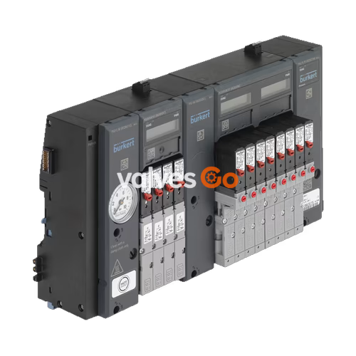
BURKERT 20045660 (Type 8647 AirLINE SP) is a modular electropneumatic valve island configured as an 11 mm station width, 12-slot Revision 2 (REV2) assembly for direct backplane integration into Siemens SIMATIC ET 200SP and ET 200SP HA distributed I/O systems. Specifically built for high-density control cabinet installations, article 20045660 incorporates an integrated electronic pressure sensor on its pneumatic supply connection unit, G 1/4 process connection ports for supply and exhaust, and bottom-facing D6 push-in working connectors.
Type 8647 eliminates intermediate wiring by mechanically and electrically docking directly alongside Siemens peripheral modules on a standard rail. Actuator control signals, diagnostic messages, channel switching states, and measured supply pressures exchange directly over the backplane bus. In field deployment, pneumatic outputs drive single-acting or double-acting process valves, hygienic diaphragm valves, and linear actuators with immediate diagnostic visibility on both local LC displays and the central engineering environment.
Article 20045660 represents the Revision 2 (REV.2) generation of Type 8647. The REV.2 platform standardizes mechanical interfaces across pneumatic components, optimizes air channel geometry, and introduces visual identifiers to prevent component mismatches during installation and servicing.
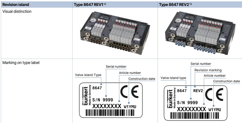
| Feature | Generation REV.1 | Generation REV.2 (Article 20045660) |
|---|---|---|
| Push-in Connector Release Rings | Black release rings | Blue release rings |
| Working Connection Arrangement | Parallel channel spacing | Wavy channel arrangement |
| Type Label Designation | Standard type code without "Rev." marking | Explicit "Rev.2" printed on type label |
| Single Valve Flange Interface | FM14 flange profile | Standardized FM20 flange profile |
| Flow Reduction with Integrated P Shut-Off | Up to 50% flow reduction | Flow reduction limited to approximately 20% |
Flange Profile Incompatibility
Single pilot valves from REV.1 (FM14 profile) and REV.2 (FM20 profile) have incompatible mechanical mounting interfaces. When replacing single pilot valves on article 20045660, select only REV.2 replacement valves equipped with FM20 flange seating.
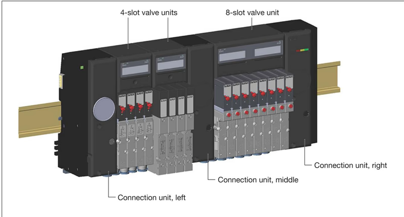
The 12-slot valve block consists of two primary functional sections: connection units (PSU modules) and valve units (PQ electronic modules assembled to matching pneumatic base modules).
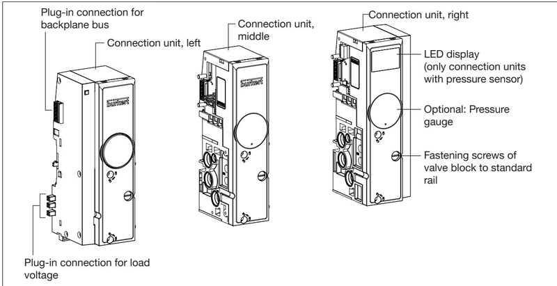
Connection units handle centralized compressed air supply and system deaeration while locking the assembly mechanically to the DIN standard rail. Article 20045660 includes 1 electronic pressure sensor module integrated into the supply section, with zero intermediate feed units required for this 12-slot length.
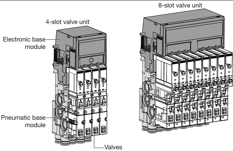
The 12 valve stations are configured using 4-slot or 8-slot base modules. Each valve slot features an 11 mm width per station.
| Parameter Group | Specification Value |
|---|---|
| Valve Island Article Number | 20045660 |
| Device Model & Type | Type 8647 AirLINE SP |
| Valve Slot Capacity | 12 stations (11 mm pitch) |
| Operating Pressure Range | 2.5 bar to 10 bar (relative) |
| Fluid Medium | Dry, filtered compressed air (oiled or unoiled), neutral gases |
| Compressed Air Quality | ISO 8573-1:2010, Class 7.4.4 (5 µm filtration recommended) |
| Medium Temperature | 0 °C to +50 °C |
| Ambient Operating Temperature | 0 °C to +55 °C |
| Air Flow Rate (QNn) | 300 l/min (Type 6524 / 6525); 200 l/min (Type 0460) |
| Electrical Supply Voltage | 24 V DC (±10%), max. residual ripple 2.4 Vss |
| Nominal Power per Valve | 0.8 W (single valve); 2 × 0.8 W with power reduction (double valve) |
| Electrical Protection Class | Class III according to DIN EN 61140, VDE 0140 |
| Ingress Protection Rating | IP20; IP65 inside closed control cabinets |
| Housing Materials | Polyamide (PA) and Polycarbonate (PC) |
| Seal Materials | NBR, FKM, and PUR |
Article 20045660 includes an integrated digital pressure sensor located in the connection unit to provide continuous continuous supply pressure monitoring without external transmitter hardware.
| Pressure [bar] | Pressure [psi] | Raw Value (Decimal) | Raw Value (Hexadecimal) | QI Bit Status |
|---|---|---|---|---|
| > 10.0 bar | > 145 psi | 0 | 0x0000 | 0 (Invalid) |
| 10.0 bar | 145 psi | 27648 | 0x6C00 | 1 (Valid) |
| 7.5 bar | 109 psi | 20736 | 0x5100 | 1 (Valid) |
| 1.0 bar | 14.5 psi | 2765 | 0x0ACD | 1 (Valid) |
| 0.0 bar | 0.0 psi | 0 | 0x0000 | 1 (Valid) |
| < 0.0 bar | < 0.0 psi | 0 | 0x0000 | 0 (Invalid) |
The 12 valve slots on 20045660 accommodate monostable flipper valves (Type 6524 and 6525) and slide valves (Type 0460). Each slot is equipped with manual override mechanisms as standard.
Unused Slot Protection
If any of the 12 stations remain unoccupied, install mechanical cover plate 661092 (REV.2) over the pneumatic port and fit electrical connection blanking plug 653670 on the electronic base module to maintain system sealing.
Type 8647 connects to the centralized plant PLC through the SIMATIC ET 200SP or ET 200SP HA interface modules (IM 155-6 PN or IM 155-6 DP).
Mounting must comply with DIN standard rail tolerances inside an industrial enclosure providing at least IP54 ingress protection.
Explore similar products in our catalog


