

PN16

BURKERT 20070084 (Type 8647 AirLINE SP) is an 8-bank pneumatic valve island with 11 mm grid, G 1/4 supply ports, D6 working connections, and direct Siemens SIMATIC ET 200SP integration.
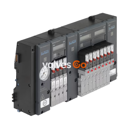
BURKERT 20070084 (Type 8647 AirLINE SP) is an 8-station modular electropneumatic valve island designed for seamless mechanical and electrical docking to Siemens SIMATIC ET 200SP and SIMATIC ET 200SP HA distributed I/O systems. Fabricated in Revision 2 (REV.2) hardware architecture with an 11 mm grid per station, the unit integrates connection units, electronic base modules (PQ modules), pneumatic base modules, and high-response pilot solenoid valves into a singular DIN-rail assembly. Operating across an operating pressure range of 2.5 to 10 bar and a medium temperature range of 0 °C to +50 °C, article 20070084 features G 1/4 primary pressure supply connections and bottom-facing D6 push-in working connections.
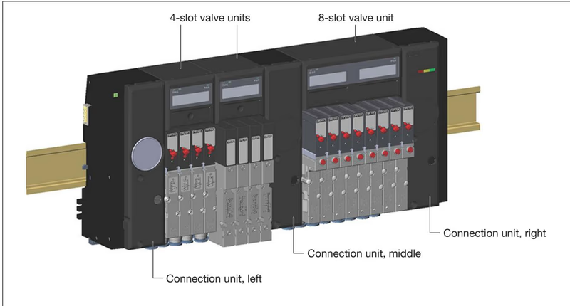
Type 8647 AirLINE SP Revision 2 incorporates optimized fluidic geometry and standardized pneumatic flange profiles across the valve deck. Revision 2 units are visually and mechanically differentiated by specific hardware indicators:
Flange Incompatibility
Single valves configured for REV.1 (flange pattern FM14/FM15) and REV.2 (flange pattern FM20/FM24) are mechanically incompatible. Replace REV.2 valve stations exclusively with REV.2 replacement valves.
| Technical Property | Specification for Article 20070084 |
|---|---|
| Valve Island Type | Type 8647 AirLINE SP (Revision 2) |
| Station Grid Width | 11 mm |
| Valve Slot Count | 8 stations |
| Valve Function Population | Mixed valve population (3/2-way and 5/2-way functions) |
| Operating Pressure Range | 2.5 bar to 10.0 bar (gauge pressure) |
| Medium Temperature Range | 0 °C to +50 °C |
| Ambient Temperature Range | 0 °C to +55 °C |
| Operating Medium | Lubricated or non-lubricated dry compressed air, neutral gases (ISO 8573-1:2010, Class 7.4.4; 5 µm filtration recommended) |
| Flow Rate ($Q_{\text{Nn}}$ value air) | 300 l/min (measured at +20 °C, 6 bar inlet pressure, 1 bar pressure drop) |
| Operating Voltage | 24 V DC (±10%), max. residual ripple 2.4 Vss |
| Nominal Power per Solenoid | 0.8 W (single valve) / 2 x 0.8 W with integrated power reduction (double valve) |
| Supply Port 1 (P) / Exhaust Ports 3 (R), 5 (S) | G 1/4 thread |
| Working Ports 2 (A), 4 (B) | Push-in coupling D6 (6 mm tube outer diameter) |
| Mounting Position | Any, preferably vertical with actuators upright |
| Ingress Protection Rating | IP20 (IP65 when housed inside an enclosed industrial control cabinet) |
| Control Cabinet Minimum Requirement | At least IP54 enclosure rating according to EN 60529 |
Type 8647 valve assemblies consist of connection units (PSU modules) flanking the perimeter and modular valve units situated along the standard mounting rail.
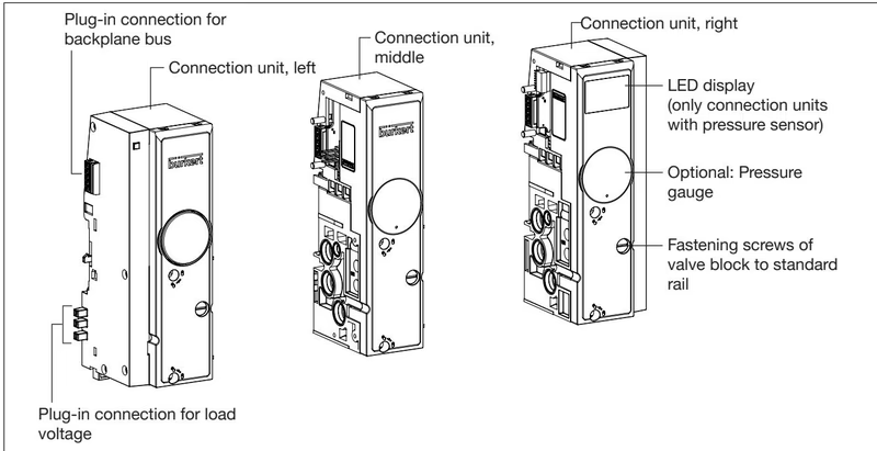
Connection units establish the pneumatic supply, auxiliary pilot control air, main exhaust deaeration, and mechanical clamping to the DIN rail:
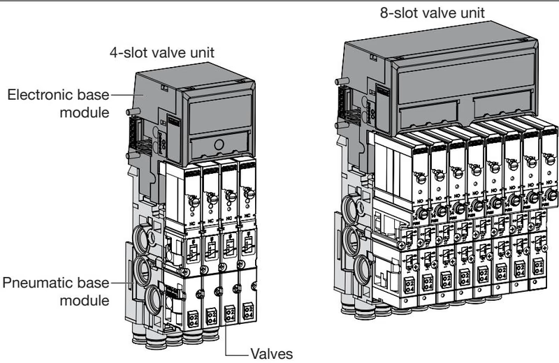
Valve units comprise three interlocking functional layers:
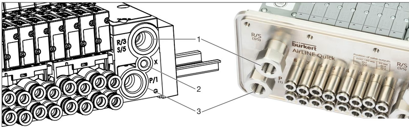
Pneumatic connections are divided into supply/exhaust connections on the connection units and working connections on the pneumatic base modules.
| Port Identification | Marking / Connection | Port Function | Recommended Tightening Torque |
|---|---|---|---|
| Port 1 | P / 1 | Compressed air pressure supply (G 1/4) | 4 to 7 Nm (max. 20 Nm) |
| Port 3 / 5 | R / 3, S / 5 | Exhaust air deaeration (G 1/4) | 4 to 7 Nm (max. 20 Nm) |
| Port X | X | Auxiliary pilot air / pilot exhaust (M5) | 1.0 to 1.2 Nm (max. 3 Nm) |
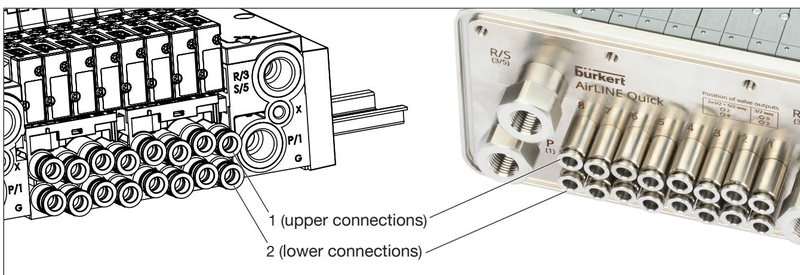
| Port 2 | Service port 2 (A) | Working port, upper or lower connection (D6 push-in) | Push-in tube engagement |
| Port 4 | Service port 4 (B) | Working port, lower connection (D6 push-in) | Push-in tube engagement |
Port Assignment Precaution
Never interchange pressure supply port 1 (P) and exhaust ports 3/5 (R/S). Pilot control exhaust port X must remain unsealed at all times to avoid operational malfunction or backpressure buildup.
Push-in connections comply with DIN ISO 14743:2020. Observe the following mechanical recommendations during tube piping:
Type 8647 automatically engages the backplane communication bus and power supply bus when latched to the adjacent Siemens SIMATIC ET 200SP BaseUnit:
Three complementary methods allow immediate de-energization of the pilot valves independent of the master fieldbus controller:
Each electronic base module incorporates two LED indicators (DIAG and PWR) along with an LCD screen displaying channel switching states, valve cycle counts, and real-time operational messages:
Wire Break Ch. x, Short Circuit Ch. x, EVS active, No supply voltage, and Pilot SCC Limit Ch. x (switching cycle counter warning limit reached).Explore similar products in our catalog


