

PN16

BURKERT 20073565 Type 8640 is an 8-bank pneumatic valve block featuring 3/2-way valve function, G 1/2 supply and G 1/4 working ports, operating at 2 to 8 bar pressure with DIN-rail mounting and IP20 protection.
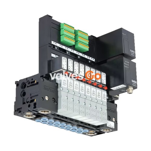
BURKERT 20073565 (Type 8640) is an 8-bank modular pneumatic valve block configured with a 33 mm station width, engineered to control neutral gases and filtered compressed air across automation applications. Operating within a pressure range of 2.00 to 8.00 bar and medium temperatures from 0.00 °C to +50.00 °C, this assembly integrates 3/2-way valve functionality into a pre-configured DIN-rail mountable block. Process pneumatic connections comprise a G 1/2 main supply port and G 1/4 working ports, providing centralized fluid distribution for eight independent pilot stages without requiring internal bus communication.

Each valve station in the block uses a pilot-operated assembly comprising a Type 6106 flipper pilot valve and a Type 5470 main body with elastomer diaphragm and seat seals. The module utilizes individual point-to-point electrical wiring (single wiring), resulting in an IP20 overall enclosure protection rating when installed in control cabinets.
BURKERT Type 8640 valve blocks group modular sub-bases and individual solenoid valves into a rigid manifold. Individual stations consist of pilot stages mounted on pneumatic base plates that share internal supply channel 1 (P) and exhaust channel 3 (R).

| Item | Designation |
|---|---|
| 1 | Pilot valve Type 6106 |
| 2 | Exhaust port 3 |
| 3 | Pressure port 1 |
| 4 | Working port 4 |
| 5 | Working port 2 |
| 6 | Manual override |
| 7 | Cable plug Type 2506 / Type 2516 |
Each valve station is equipped with a mechanical manual override on the pilot body to permit manual actuation during commissioning and servicing. To engage the override, press the yellow button down and rotate it 90° clockwise until it hits the mechanical stop. The override locks in position and does not reset automatically.
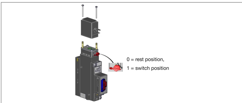
Manual Override Safety
Operate the manual override only when the electrical power is disconnected. Prior to initiating electrical control, ensure the manual override is returned to the 0 (disengaged) position.
Pneumatic connections conform to standard industrial designations molded directly on the components:
| Connection Number | Designation | Physical Thread (Article 20073565) |
|---|---|---|
| 1 | Pressure supply port (P) | G 1/2 |
| 2 and 4 | Working ports (B and A) | G 1/4 |
| 3 | Exhaust port (R) | G 1/2 (shared rail return) |
BURKERT 20073565 operates in 3/2-way circuit functions, providing directional flow control for single-acting pneumatic actuators or pilot circuits. The internal valve geometry supports standard circuit configurations:
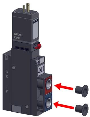
To convert a 4/2-way basic valve body to a 3/2-way function, install an airtight threaded stopper into port 2 or port 4 as indicated below:
| Port 2 | Port 4 | Resulting Circuit Function |
|---|---|---|
| Closed with stopper | Open | Function C (3/2-way, normally closed) |
| Open | Closed with stopper | Function D (3/2-way, normally open) |
| Specification | Parameter Value |
|---|---|
| Type | 8640 |
| Article Number | 20073565 |
| Station Configuration | 8-bank (8 valve positions) |
| Station Width (Add-on Dimension) | 33 mm |
| Valve Function | 3/2-way |
| Pressure Port 1 (P) | G 1/2 |
| Working Ports 2 (B) / 4 (A) | G 1/4 |
| Nominal Operating Pressure Range | 2.00 bar to 8.00 bar |
| Pilot Pressure Requirement | 2.00 to 10.00 bar (must be at least 70% of operating pressure) |
| Minimum Differential Pressure (Ports 1 to 3) | 2.00 bar |
| Medium Temperature Range | 0.00 °C to +50.00 °C |
| Ambient Operating Temperature | 0.00 °C to +55.00 °C |
| Fluid Compatibility | Filtered compressed air (particle size max. 10 µm), neutral gases (5 µm filtration) |
| Lubrication Condition | Preferably unlubricated (operation with lubricated air permissible) |
| Seal Material | NBR (Nitrile butadiene rubber) |
| Mounting Base Style | Standard rail installation (DIN rail EN 50022) |
| Communication / Fieldbus | None (single direct wiring) |
| Digital Input Count | 0 PCE |
| Intermediate Supply Modules | 0 PCE |
| Manual / Automatic Electrical Switching | No |
| Integrated Check Valves in 3 (R) / 5 (S) | No |
| Pneumatic HotSwap in 1 (P) | No |
| Enclosure Protection Class | IP20 (with single wiring connectors) |
| Storage Temperature | -40.00 °C to +55.00 °C |
BURKERT 20073565 is pre-assembled as an 8-station valve manifold using modular pneumatic sub-bases held together with integrated latch hooks and tabs.
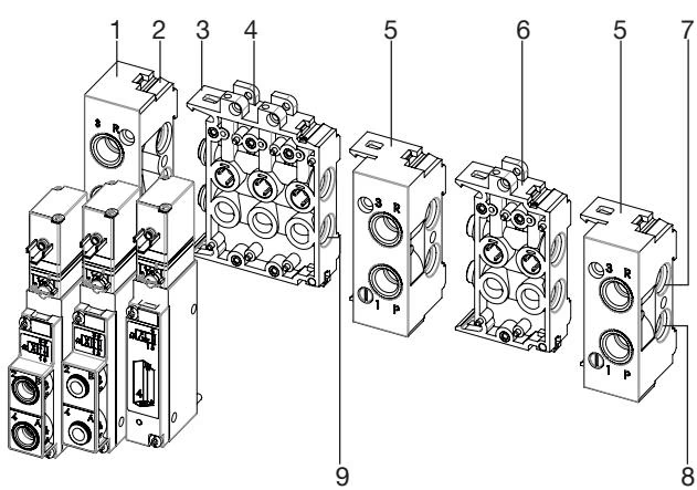
Seal Integrity
Crushed, pinched, or missing O-rings between base blocks or on the valve mounting face will result in pressure loss and leaky manifolds. Never tighten mounting screws if seals are displaced.
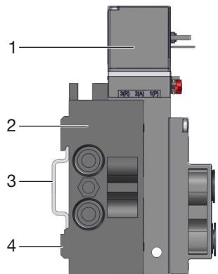
The complete block secures directly onto a standard DIN mounting rail complying with EN 50022 (35 x 15 mm or 35 x 7.5 mm):
If the electrical connector clearance requires adjustment, the solenoid pilot coil can be rotated 180°:
Pneumatic supply lines must be blown clean before attachment. If line contamination is suspected, install a 5 µm filter immediately upstream of port 1 (P).
| Port Thread Size | Function / Marking | Recommended Torque [Nm] | Maximum Torque [Nm] |
|---|---|---|---|
| G 1/4 | Supply P, Exhaust R/S | 4 to 7 | 20 |
| G 1/8 | Working lines A/B, Pilot feeds | 3 to 6 | 7 |
| Hose Outer Diameter (OD) | Polyamide (PA) Min. Tensile Force [N] | Polyurethane (PU) Min. Tensile Force [N] |
|---|---|---|
| 3 mm (1/8") | 60 | 25 |
| 4 mm (5/32") | 70 | 50 |
| 6 mm (1/4") | 120 | 100 |
| 8 mm (5/16") | 170 | 150 |
| 10 mm (3/8") | 250 | 200 |
| 12 mm (1/2") | 300 | 200 |
| 14 mm | 300 | 250 |
| 16 mm (5/8") | 350 | 300 |
Flexible Hose Retention
When utilizing soft polyurethane (PU) tubing under high working pressures, insert support sleeves (ID 20099400) inside the hose end to maximize radial retention and eliminate pull-out risks.
Each solenoid coil connects via individual industrial form C cable plugs (such as Type 2516 / DIN EN 175301-803 Form C) fastened with a central screw.

| Parameter | Protective Conductor Test Specification |
|---|---|
| Maximum Earth Resistance | 0.1 Ω |
| Test Voltage | 12 V |
| Test Current | 1 A |
Prior to pressurization, verify that all pneumatic fittings and M4/M2 fasteners are torqued to specification. Supply voltage must match the coil rating, and the manual override screws must be unlocked.
| Fault Condition | Probable Cause | Corrective Action |
|---|---|---|
| Valve fails to switch | Operating voltage absent or below tolerance | Check wiring terminals; verify supply voltage matches type label within ±10%. |
| Manual override locked in non-zero position | Rotate manual override 90° counter-clockwise to zero position. | |
| Supply pressure insufficient (< 2 bar) | Increase upstream volume and pressure; ensure minimum supply pressure is ≥ 2.0 bar. | |
| Delayed switching or continuous venting at exhaust 3 | Operating pressure below pilot threshold | Establish large-volume air reservoir; ensure operating pressure is ≥ 2.0 bar. |
| Valves energized prior to pneumatic pressure build-up | Apply full pneumatic pressure to port 1 before applying electrical switching signals. | |
| Exhaust port backpressure due to clogged silencer | Clean clogged silencers, replace with high-flow mufflers, or expand exhaust lines. | |
| Contaminants or debris inside pilot or main chamber | Blow compressed air in reverse pulses through exhaust ducts, or replace affected pilot/valve. | |
| External air leakage between modules | Missing, pinched, or damaged inter-module O-rings | Disassemble base block and replace damaged O-rings between sub-bases. |
| External leakage under valve body | Damaged or misaligned flat seat seals | Remove valve, verify correct gasket seating, and retorque screws to 0.6 Nm. |
Before disassembling the valve manifold, isolate the pneumatic pressure supply, vent all lines, and disconnect all electrical power sources.
Explore similar products in our catalog


