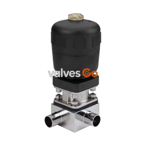
Type 2032

BURKERT 20075525 (Type 2935) manually operated tank bottom diaphragm valve. Features DN 150 flange connection, EPDM high-temperature diaphragm, and stainless steel block body.
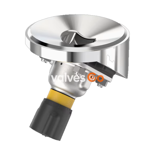
BURKERT 20075525 (Type 2935) manually operated diaphragm valve consists of a manually operated actuator, a diaphragm, and a tank bottom valve body. The manual actuator with a plastic or stainless steel handwheel is available with a diaphragm bonnet made of stainless steel or plastic, ensuring reliable use in hygienic or aggressive ambient conditions. The flow-optimised valve body with minimum dead space enables high flow values and a wide range of possible applications. The actuator has a compact, autoclavable design and is equipped with an integrated visual position indicator, a reproducible stroke scale, and an adjustable closing limiter.
This specific configuration (SKU 20075525) features a DN 150 Bürkert-tank bottom flange, an EPDM high-temperature diaphragm (size 40), and a stainless steel block body (1.4435 / 316L). It is rated for pressures up to 10 bar and is fully CIP/SIP capable, meeting stringent food and pharmaceutical standards including FDA and USP Class VI.
| Feature | Specification |
|---|---|
| Block body material | Stainless steel block material 1.4435 (DIN EN 10088) and 316L (ASME BPE) |
| Diaphragm material | EPDM high-temperature |
| Actuator material | PPS (Polyphenylene sulphide) handwheel, Stainless steel bonnet |
| Standard surface quality | Internally electrically polished: Ra ≤ 0.38 μm (ASME BPE SF4/DIN HE4) |
| Medium temperature | -10...+143 °C (steam sterilisation +150 °C for 60 min) |
| Ambient temperature | -10...+130 °C (short-term up to +150 °C), autoclavable |
| Nominal pressure | 0 - 10 bar (PN 16 / Class 150) |
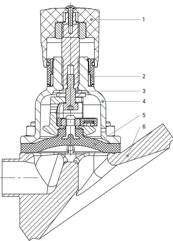
| No. | Element | Material |
|---|---|---|
| 1 | Handwheel | Polyphenylene sulphide (PPS), stainless steel 1.4308 |
| 2 | Visual position indicator | Polyamide (PA), stainless steel 1.4305 |
| 3 | Valve spindle | Stainless steel 1.4305 |
| 4 | Diaphragm bonnet | Stainless steel 1.4308, polyphenylene sulphide (PPS) |
| 5 | Diaphragm | EPDM (AD), PTFE/EPDM (EA), advanced PTFE/EPDM (EU), laminate of GYLON® and EPDM (ER) |
| 6 | Valve body | Stainless steel block material |
(Dimensions in mm, unless otherwise stated)
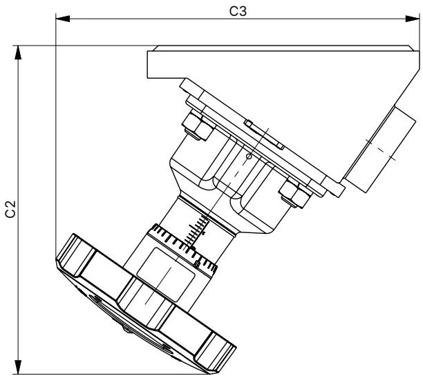
| Diaphragm size | C2 | C3 |
|---|---|---|
| 8 | 69 | 71 |
| 15 | 103 | 101 |
| 20 | 116 | 115 |
| 25 | 127 | 129 |
| 40 | 182 | 201 |
| 50 | 203 | 217 |
| 65 | 265 | 305 |
| 80 | 336 | 278 |
| 100 | 300 | 370 |
INFO
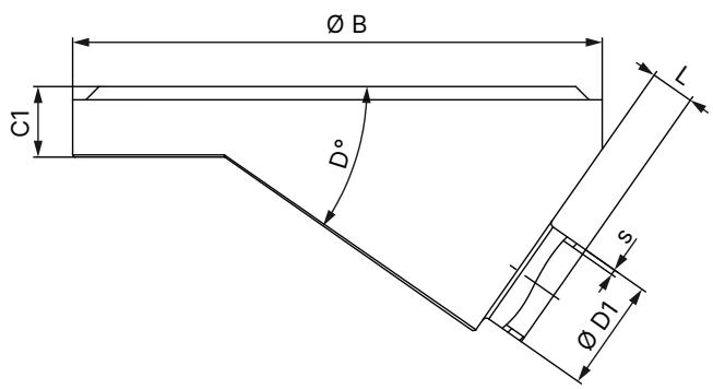
Clamp dimensions must be added to the welded connection dimensions.
DANGER
Risk of injury due to high pressure and escaping medium. Switch off the pressure before working on the device or system. Vent or empty the lines.
Observe the following sequence:
TIP
For information on containers and instructions for welding, refer to the ASME VIII Division I standard. Check the batch number indicated on the manufacturer’s certificate 3.1 supplied before starting welding work.
WARNING
Before welding, note the following:
WARNING
Turn the handwheel only until you can feel the valve closing. Do not tighten any further. The diaphragm may be damaged.
| Diaphragm size | Medium pressure [bar] | Tightening torque (Static) EPDM/FKM [Nm] | Tightening torque (Static) PTFE [Nm] |
|---|---|---|---|
| 8 | 10 | 0.6 | 1.1 |
| 15 | 10 | 0.8 | 1.7 |
| 20 | 10 | 0.9 | 3.0 |
| 25 | 10 | 1.2 | 3.5 |
| 32 | 10 | 2.5 | 4.0 |
| 40 | 10 | 4.5 | 7.0 |
| 50 | 10 | 6.0 | 11.0 |
| 65 | 10 | 8.0 | 23.0 |
| 80 | 10 | 12.0 | 21.0 |
| 100 | 6 | 11.0 | 22.0 |
(A tolerance of +10% applies to the tightening torques.)

DANGER
Explosion risk due to electrostatic charge! If statically charged devices or persons discharge suddenly, there is an explosion risk in the potentially explosive area.
Device Grounding:
Explore similar products in our catalog