
Transit-Time Ultrasonic

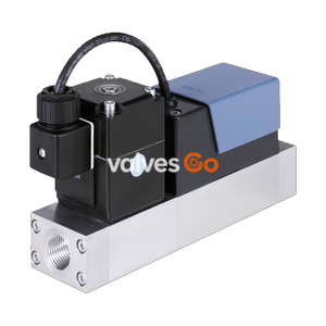
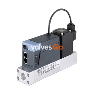
BURKERT 20121211 (Type 8741) is a thermal gas mass flow controller with Type 2871 proportional valve, 0.20 Nl/min range for O2/N2/air, G 1/4" ports, CANopen communication, and 24 V DC supply.
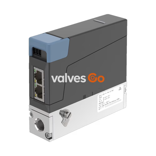
BURKERT 20121211 (Type 8741) is a thermal mass flow controller (MFC) for gases, engineered for dosing and closed-loop flow control in industrial installations. The instrument combines a thermal MEMS sensor situated directly in the gas bypass channel with a direct-acting Type 2871 proportional valve featuring an orifice diameter of 0.2 mm. Calibrated on air with an operating nominal flow rate of 0.20 Nl/min, this specific controller is rated for oxygen, nitrogen, and clean air under a nominal operating pressure of 2 bar(g) and a maximum inlet pressure of 3 bar(g) with 0 bar(g) outlet pressure at nominal flow.
Configured with an aluminium fluidic body and G 1/4" internal thread process connections, BURKERT 20121211 provides a control and measuring span of 1:200 with an overall settling time t95 under 300 ms. Fluid seals and valve seat seals are manufactured from fluororubber (FKM). Electrical interfacing is established via a 4-pin plug-in terminal block supporting digital communication over CANopen and the proprietary Bürkert Systembus (büS) at 24 V DC operating voltage, with status monitoring provided by an integrated RGB LED conforming to NAMUR NE 107.
BURKERT 20121211 integrates the sensor module, digital control electronics, fluid block, and electromagnetic actuator in an IP20 housing structure designed for horizontal mounting.
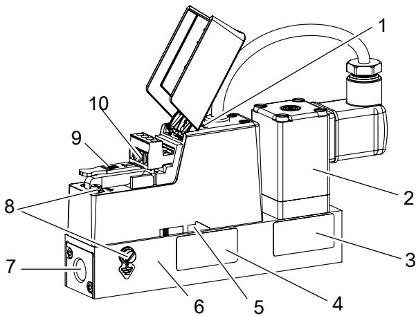
| Component Callout | Component Name | Description / Functional Specification |
|---|---|---|
| 1 | Status indicator | Multi-colour RGB LED providing optical status signaling per NAMUR NE 107 |
| 2 | Proportional valve | Type 2871 direct-acting proportional valve actuator (normally closed, seat 0.2 mm) |
| 3 | Type label | Identification plate with article number 20121211, serial number, voltage, and gas ratings |
| 4 | Calibration label | Calibration specifications including calibration gas (Air), test pressure, and date |
| 5 | Flow direction marking | Arrow indicating permitted gas flow direction through the fluidic body |
| 6 | Base block | Aluminium fluid manifold accommodating sensor channel and valve seat |
| 7 | Medium connection | Process connection ports with G 1/4" internal thread conforming to DIN ISO 228/1 |
| 8 | Functional earth connection | M4 grounding terminal screw on the lateral housing surface |
| 9 | Slot for memory card | Slot for micro configuration memory card for parameter backup and replacement |
| 10 | Electrical connection | 4-pin plug-in terminal block with 5.08 mm pitch for CANopen/büS and 24 V DC power |
| Specification Parameter | Technical Value / Standard |
|---|---|
| Article number (Order code) | 20121211 |
| Type family | 8741 |
| Device function | Mass flow controller (MFC) |
| Calibrated medium | Air (Index N: 1.013 bar abs, 0 °C) |
| Permissible operating gases | Neutral, pure gases: Air, Nitrogen (N2), Oxygen (O2) |
| Nominal flow rate range (Qnom) | 0.20 Nl/min |
| Measuring and control span | 1:200 (operating range 0.20 Nl/min down to 0.001 Nl/min) |
| Nominal operating inlet pressure (p1) | 2 bar(g) |
| Outlet pressure at Qnom (p2) | 0 bar(g) |
| Maximum medium pressure | 3 bar(g) |
| Measuring accuracy | ±0.8% of reading ±0.3% of full scale (under calibration conditions after warm-up) |
| Repeatability | ±0.1% of full scale |
| Settling time t95 (MFC) | < 300 ms |
| Actuator model | Bürkert Type 2871 proportional valve |
| Valve position | Normally closed (NC) when de-energized |
| Valve seat orifice diameter | 0.2 mm |
| Fluidic base block material | Aluminium |
| Valve seat sealing material | FKM (fluororubber) |
| External sealing material | FKM (fluororubber) |
| Wetted internal materials | Stainless steel 1.4310, 1.4113, 1.4305; Aluminium; FKM |
| Process port connection | G 1/4" internal thread (DIN ISO 228/1) |
| Mounting orientation | Horizontal |
| Operating voltage | 24 V DC (±10%, residual ripple < 2%) |
| Power consumption | Maximum 3 to 19.5 W (depending on proportional valve control output) |
| Digital bus interface | CANopen and büS (switchable via software) |
| Field wiring connection | 4-pin plug connector (screw terminals, 5.08 mm grid) |
| Enclosure rating | IP20 |
| Ambient operating temperature | -10 °C to +50 °C |
| Medium operating temperature | -10 °C to +70 °C (-10 °C to +60 °C for gaseous oxygen) |
| Storage temperature range | -10 °C to +70 °C |
| Relative air humidity | < 95% at +55 °C, non-condensing |
| Weight | Approximately 500 g |
Flow rate acquisition operates via a bypass measurement path. A laminar flow element mounted inside the main flow passage generates a small differential pressure, directing a defined fraction of the gas through the sensor channel.
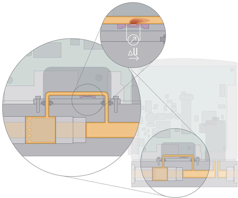
The measurement channel features a silicon MEMS chip with an etched membrane. A central heating resistor supplied with a constant voltage is surrounded by one upstream and one downstream temperature sensor. Gas passing across the chip induces an asymmetric temperature gradient. The resulting differential voltage across the two sensors is directly proportional to the mass flow rate.
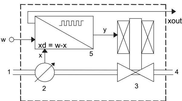
In closed-loop operation, the microcontroller compares the measured mass flow rate value x with the digital set-point value w supplied over CANopen or büS. The electronics calculate the control variable y and output an electrical current to the coil of the direct-acting Type 2871 proportional valve, adjusting the valve opening to match the setpoint within t95 < 300 ms.
Operating Precautions During Autotune
While the Autotune function is running, the actual mass flow rate can exceed the nominal flow rate value. Ensure process downstream lines can safely tolerate flow increases before triggering Autotune. Do not interrupt the 24 V DC electrical power supply and keep upstream pressure constant throughout the routine.
BURKERT 20121211 requires clean and dry gases. Contaminants and liquid condensates impair thermal transfer across the MEMS chip and compromise the tight shut-off capability of the 0.2 mm valve seat.
| Medium Quality Criterion | Standard Reference (DIN ISO 8573-1) | Permissible Limit Value |
|---|---|---|
| Solid particle size | Quality class 2 | Maximum 1 µm |
| Solid particle density | Quality class 2 | Maximum 1 mg/m³ |
| Pressure dew point | Quality class 4 | Maximum +3 °C |
| Oil concentration | Quality class 1 | Maximum 0.01 mg/m³ |
Upstream Filtration Recommendation
If media contamination or pipe scale cannot be excluded, install an upstream inline filter with a mesh size smaller than 25 µm directly before the device inlet to protect the sensor bypass and valve seat.
For operation with gaseous oxygen, the manufacturer declaration confirms material suitability within the medium temperature limit of -10 °C to +60 °C. Nominal inlet pressure for model 20121211 is calibrated at 2 bar(g). The maximum allowed inlet pressure is 3 bar(g), and the outlet pressure at Qnom is 0 bar(g).
Electrical connection is established via a 4-pin screw terminal block with a 5.08 mm pitch.
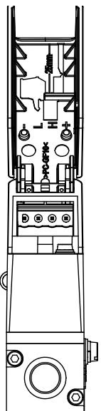
| Terminal Pin | Signal Designation | Wire Colour (Bürkert büS Cable) | Functional Description |
|---|---|---|---|
| 1 | DGND | Black | Digital ground and power supply return |
| 2 | CAN_L | Blue | CAN low differential signal line |
| 3 | CAN_H | White | CAN high differential signal line |
| 4 | +24 V DC | Red | Operating power supply +24 V DC (±10%) |
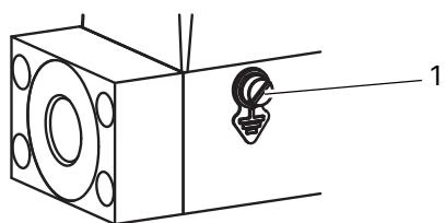
Functional earthing (FE) must be connected to the M4 grounding screw on the side of the housing using a ring cable lug and a green-and-yellow ground conductor. The wire cross-section must be equal to or greater than the power supply cable cross-section. Tighten the M4 screw to 1.8 to 2.0 N·m (1.33 to 1.47 lbf·ft).
Functional Earthing Requirement
Failure to connect the functional earthing terminal to ground voids compliance with the EMC Directive and creates electrostatic discharge risks in explosive or combustible atmospheres. Always ground the device housing prior to energizing the bus.
For UL-listed installations, supply the instrument via a Limited Energy Circuit (LEC) per UL/IEC 61010-1, a Limited Power Source (LPS) per UL/IEC 60950, or an NEC Class 2 power supply unit.
Device configuration, calibration checks, and live data logging are performed through the Bürkert Communicator software (Type 8920) running on Windows PCs. Connection is made with the USB-büS interface set 1 (article 772426), which includes an M12-to-terminal cable and an integrated 120 Ω bus terminating resistor.
Flush Mode Duration Limit
Operating the proportional valve at 100% continuous opening increases internal coil temperature. Do not keep the valve in flush mode continuously for more than 10 minutes to prevent thermal overload.
The RGB status LED displays operating and alarm conditions according to NAMUR recommendation NE 107. If several diagnostic states occur simultaneously, the indicator displays the state with the highest priority.
| LED Colour | Code | NAMUR Status Signal | Description and Required Operator Action |
|---|---|---|---|
| Red | 5 | Failure | Device malfunction or supply voltage out of specification. Check wiring and 24 V DC supply. |
| Orange | 4 | Function check | Calibration in progress, Autotune active, or device in manual / open-loop test mode. |
| Yellow | 3 | Out of specification | Temperature or supply voltage beyond limits; valve position reached 100% without achieving setpoint. |
| Blue | 2 | Maintenance required | Normal operation active, but internal diagnostics indicate scheduled servicing or calibration check. |
| Green | 1 | Diagnosis active | Device operates normally without error; diagnostics running in background. |
| White | 0 | Diagnosis passive | Device powered on; diagnostic functions passive. |
| Fault Condition | Probable Cause | Corrective Action |
|---|---|---|
| LED solid red | Supply voltage deviation or CAN communication severed | Verify 24 V DC ±10% voltage at terminals 1 and 4; verify bus wiring and terminating resistor. |
| LED flashing | Device identified in Bürkert Communicator | Normal optical acknowledgement during active software selection. |
| Unstable mass flow reading | Missing functional ground or excessive voltage ripple | Connect M4 functional ground; ensure supply voltage residual ripple remains below 2%. |
| Medium flows at 0% setpoint | Operating pressure exceeds tight-sealing limit | Reduce inlet pressure to calibrated 2 bar(g); clean valve seat if contaminated. |
| Setpoint not reached | Inlet pressure too low or mesh filter clogged | Check inlet pressure; inspect and clean the stainless steel inlet mesh filter. |
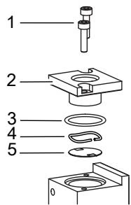
BURKERT 20121211 requires no routine maintenance when handling pure, dry gases conforming to DIN ISO 8573-1. Under harsh operating conditions, inspect and clean the integrated stainless steel mesh filter located at the fluid inlet.
| Accessory Description | Order Article Number |
|---|---|
| USB-büS interface set 1 (Type 8923) with power supply and cables for Bürkert Communicator | 772426 |
| USB-büS interface set 2 (Type 8923) with micro-USB adapter cable | 772551 |
| 4-pin terminal connector (replacement, 5.08 mm pitch) | 565876 |
| 4-pin terminal connector with integrated 120 Ω terminating resistor | 566066 |
| Bürkert büS connection cable, 50 m reel | 772413 |
| Bürkert büS connection cable, 100 m reel | 772414 |
| DIN rail power supply unit Type 1573 (100–240 V AC / 24 V DC, 1 A, NEC Class 2) | 772361 |
| DIN rail power supply unit Type 1573 (100–240 V AC / 24 V DC, 2 A, NEC Class 2) | 772362 |
| DIN rail power supply unit Type 1573 (100–240 V AC / 24 V DC, 4 A) | 772363 |
| Stainless steel compression fitting G 1/4" to 6 mm tube | 901538 |
| Stainless steel compression fitting G 1/4" to 8 mm tube | 901540 |
| Stainless steel compression fitting G 1/4" to 1/4" tube | 901551 |
| Stainless steel compression fitting G 1/4" to 3/8" tube | 901553 |
| Copper sealing ring for G 1/4" compression fitting | 901575 |
| Rubber-steel sealing ring for G 1/4" compression fitting | 901579 |
Explore similar products in our catalog