

PN16

BURKERT 20135194 Type 8640 is a 6-bank modular pneumatic valve block with 33 mm station width, G 1/2 supply, G 1/4 working ports, DIN-rail mounting, 2 to 8 bar pressure rating, and IP20 protection.
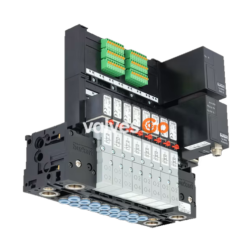
BURKERT 20135194 (Type 8640) is a 6-bank modular pneumatic valve block configured with a 33 mm station width, G 1/2 main supply port, and G 1/4 working ports positioned opposite the pneumatic supply side. Built on the Type 8640 modular architecture, this pre-configured assembly uses polyamide (PA) base bodies joined by integrated latching mechanics for rapid assembly and standard DIN-rail installation. Designed for direct individual actuation without internal bus communications or digital fieldbus nodes, article 20135194 delivers localized control across pneumatic pressures ranging from 2.00 bar to 8.00 bar at media operating temperatures from 0.00 °C to 50.00 °C.

| Specification Parameter | Technical Value / Characteristic |
|---|---|
| Article Number | 20135194 |
| Valve Island System Type | Type 8640 |
| Valve Island Setup | 6-bank pneumatic valve block |
| Station Pitch / Width | 33 mm |
| Main Supply Connection 1 (P) | G 1/2 |
| Working Ports 2 (B) and 4 (A) | G 1/4 |
| Working Port Alignment | Opposite of supply side |
| Nominal Operating Pressure | 2.00 bar to 8.00 bar (overpressure to atmospheric) |
| Fluid Medium Temperature | 0.00 °C to +50.00 °C |
| Permissible Ambient Temperature | 0.00 °C to +55.00 °C |
| Permissible Storage Temperature | -20 °C to +60 °C (-40 °C to +55 °C in transport packaging) |
| Modular Variant & Communication | Without bus communication (due to single wiring) |
| Digital Inputs | 0 PCE |
| Intermediate Supply Feed Quantity | 0 PCE |
| Manual / Automatic Switching | No |
| Integrated Check Valves (Exhaust 3/5) | No |
| Pneumatic HotSwap Function | No |
| Mechanical Installation Mode | DIN-rail mounting (Standard rail EN 50022 35 x 7.5 or 35 x 15) |
| Ingress Protection Rating | IP20 (max. with suitable connection) |
| Body Material | High-grade Polyamide (PA) |
| Operating Medium | Compressed air (ISO 8573-1:2010, Class 7.4.4) or neutral gases |
Type 8640 valve block assemblies are structured from modular sub-units that interlock mechanically using precision latch tabs and latch grooves. The 6-station pneumatic manifold forms a rigid, leak-tight rail once the modules are locked together.
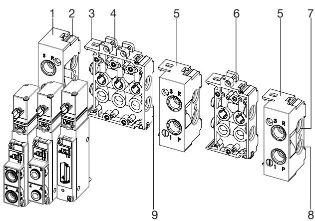
| Item | Designation | Functional Role |
|---|---|---|
| 1 | Left connection module | Pneumatic feed termination and side anchoring |
| 2 | Latch tab | Front/top alignment and structural engagement point |
| 3 | Latch hook | Lower locking hook engaging preceding module groove |
| 4 | Base modules (e.g. 3-fold) | Intermediate pneumatic base carrier for valve stations |
| 5 | Right connection module | Right-side end termination and optional supplemental porting |
| 6 | Base modules (e.g. 2-fold) | Paired pneumatic base carrier block |
| 7 | Exhaust channel 3 (R) | Common venting manifold channel |
| 8 | Supply channel 1 (P) | Primary pressurized air delivery conduit |
| 9 | O-ring | Module-to-module port sealing ring |
Assembly procedure steps:
Sealing Integrity Warning
Crushed O-rings, twisted profile seals, or contaminated sealing channels will result in unsealed manifolds and continuous pneumatic leakage. Check all elastomeric elements prior to snapping modules together.
Article 20135194 is factory-configured for DIN-rail installation. The base profile hooks onto a top edge and secures via clamping mechanisms.
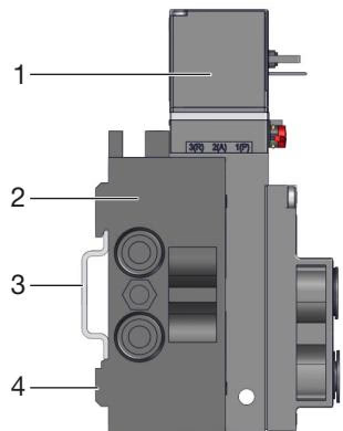
Standard DIN-rail installation procedure:
When screwing pneumatic fittings into threaded ports, do not exceed maximum permissible torques:
| Port Size | Port Marking & Circuit Assignment | Recommended Torque | Maximum Permissible Torque |
|---|---|---|---|
| G 1/4 / NPT 1/4 | Supply port 1 (P), Exhaust ports 3 (R) / 5 (S) | 4 to 7 Nm | 20 Nm |
| G 1/8 / NPT 1/8 | Working ports 2 (B) / 4 (A), auxiliary ports | 3 to 6 Nm | 7 Nm |
Tool Safety Restriction
Never utilize the valve solenoid coil or pilot body as a lever arm when tightening process connections or hose fittings. Always grip the port housing directly with appropriate wrenches.
The pilot valves require a minimum internal working pressure of 2.0 bar (up to 8.0 bar max). The differential pressure between supply port 1 and exhaust port 3 must remain at or above 2.0 bar at all times for reliable pilot shifting. Supply media must consist of dry, filtered compressed air adhering to ISO 8573-1:2010 Class 7.4.4 (5 µm particle filtration recommended).
When using push-in hose connectors, the tubing must meet DIN 73378 outside diameter tolerances and have a minimum material hardness of 40 Shore D (DIN 53505 / ISO 868). Hoses must be cut square, burr-free, and inserted fully into the fitting until seated behind the internal retaining claws.
| Hose Outside Diameter (OD) | Minimum Tensile Force (PA Hose) | Minimum Tensile Force (PU Hose) |
|---|---|---|
| 3 mm (1/8" / 3.17 mm) | 60 N | 25 N |
| 4 mm (5/32" / 4 mm) | 70 N | 50 N |
| 6 mm (1/4" / 6.35 mm) | 120 N | 100 N |
| 8 mm (5/16" / 8 mm) | 170 N | 150 N |
| 10 mm (3/8" / 9.52 mm) | 250 N | 200 N |
| 12 mm (1/2" / 12.7 mm) | 300 N | 200 N |
| 14 mm | 300 N | 250 N |
| 16 mm (5/8" / 16 mm) | 350 N | 300 N |
Hose Retention Optimization
When flexible polyurethane (PU) tubing is utilized under dynamic vibrations or pressure cycling, insert stainless support sleeves (Bürkert ID 20099400) inside the tube ends to reinforce holding stability and prevent wall collapse.
Article 20135194 is built without bus communication and operates using single wiring. Solenoid connections utilize individual cable plugs complying with DIN EN 175301-803 Form C (such as Type 2516).
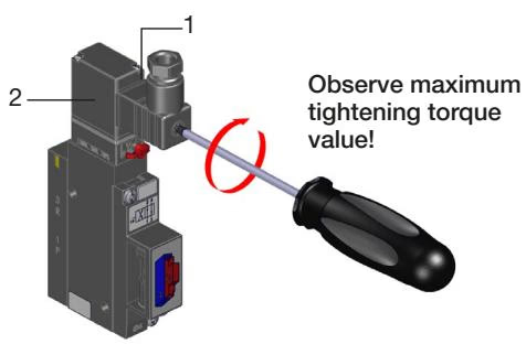
Single-wiring electrical rules:
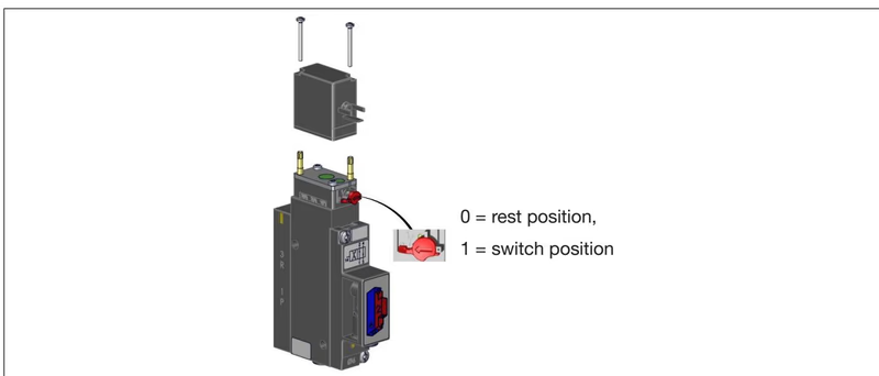
To actuate the valve mechanically during testing:
Verify supply voltage, operating line pressure (2 to 8 bar), port assignments, and unlocked manual overrides prior to applying power.
| Operating Fault | Underlying Root Cause | Corrective Remedy |
|---|---|---|
| Valve fails to switch | Operating voltage absent or below ±10% tolerance band | Verify supply voltage on cable terminals according to type label rating. |
| Manual override locked in actuated position | Turn override counter-clockwise 90° to reset to neutral zero position. | |
| Line pressure absent or below 2.0 bar pilot threshold | Establish stable supply pressure (minimum operating pressure ≥ 2.0 bar). | |
| Delayed switching or continuous exhaust blow-off | Upstream supply line restricted or insufficient buffer capacity | Install large-volume air reservoir and remove line restrictions. |
| Valves energized during system pneumatic pressure build-up | Apply full pneumatic pressure to the manifold before switching pilot valves. | |
| Excessive back pressure in exhaust due to clogged silencers | Clean or replace silencer elements; use larger expansion mufflers. | |
| Particulate contamination within valve body | Apply short pressure pulses to purge contaminants, or replace valve unit. | |
| External leakage around block | Missing, misaligned, or pinched O-rings between modules | Disassemble sub-block and fit fresh, lubricated modular O-rings. |
| Valve seat flat gasket damaged or missing | Remove valve screws, insert replacement flat seal, torque to 0.6 Nm. |
Residual Energy Hazard
Always isolate and discharge all compressed air supplies, vent all connected pneumatic circuits, and de-energize electrical power prior to commencing disassembly work on the Type 8640 block.
Manifold removal and dismantling procedure:
Explore similar products in our catalog


