Type 2032

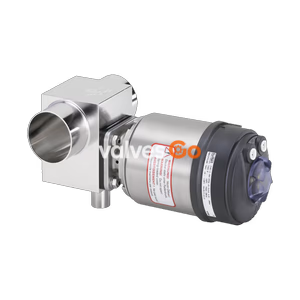
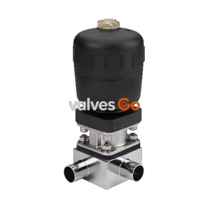
BURKERT 20136039 (Type 2973) manual 2/2-way diaphragm valve features a forged 316L BN2 body, DN 25 SMS 3008 weld ends, Advanced PTFE/EPDM diaphragm, 10 bar rating, and PPS handwheel.
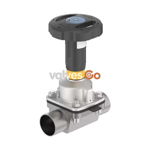
BURKERT 20136039 (Type 2973) is a manually operated 2/2-way diaphragm valve built for hygienic, sterile, and demanding process applications. Configured with FullFunction manual actuation, article 20136039 incorporates a zero-deadleg forged stainless steel 316L / 1.4435 BN2 body (VS), DN 25 welded spigots conforming to SMS 3008 (tube diameter 25.0 x 1.2 mm), and an Advanced PTFE diaphragm backed by EPDM. The valve provides tight isolation from 0 to 10 bar over a medium temperature span of -5 °C to +143 °C, with steam sterilisation capability up to +150 °C for 60 minutes.
The Type 2973 manual actuator combines a polyphenylene sulphide (PPS) handwheel with an investment-cast stainless steel 1.4308 bonnet. It is autoclavable and resistant to harsh washdowns, aggressive process media, and corrosive plant environments. The internal fluid contact geometry is free from dead zones, delivering a water flow coefficient of Kv = 14.8 m³/h (Cv = 17.2 gpm). The assembly complies with EC Regulation 1935/2004, FDA 21 CFR, and USP Class VI, and satisfies ATEX / IECEx mechanical explosion protection standards for equipment category 2 in Gas Zone 1 and Dust Zone 21.
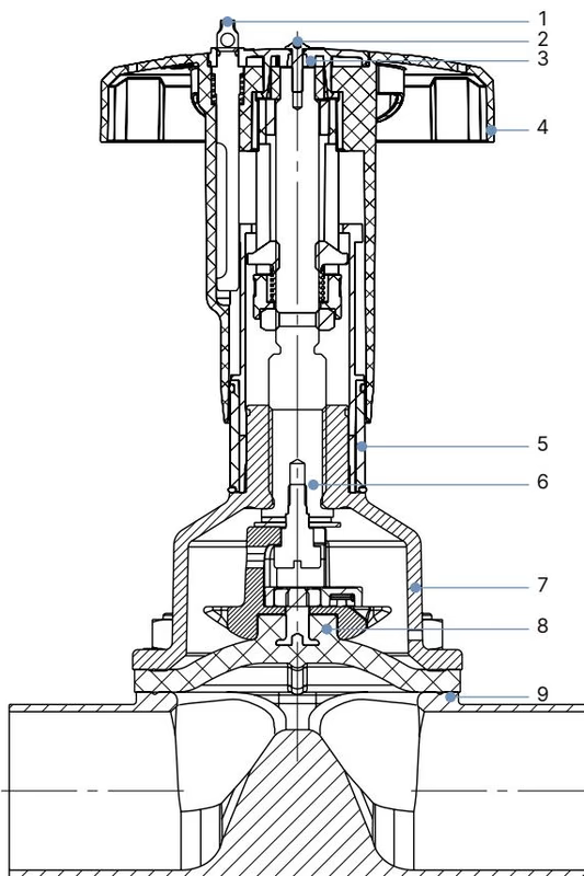
Every structural part in contact with either the fluid or external cleanroom ambient conditions is selected for chemical inertness and mechanical stability:
| Item | Component | Material |
|---|---|---|
| 1 | Lock pin | Stainless steel 1.4305 |
| 2 | Fastening screw | Stainless steel A2 |
| 3 | Handwheel cover | Polyamide (PA) |
| 4 | Handwheel | Polyphenylene sulphide (PPS) |
| 5 | Visual position indicator | Polyamide (PA) |
| 6 | Valve spindle | Stainless steel 1.4305 |
| 7 | Diaphragm bonnet / socket | Stainless steel 1.4308 |
| 8 | Diaphragm | Advanced PTFE with EPDM backing (material code EU / P06) |
| 9 | Valve body | Forged stainless steel 316L / 1.4435 BN2 (VS) |
Surface Quality
The forged steel body (VS) features an internal surface electropolished to Ra ≤ 0.38 µm (Bürkert code NO17, conforming to ASME BPE SF4 and DIN HE4). The exterior forged surface is mechanically and electropolished. The valve includes an EN 10204 3.1 inspection certificate for the body and a 2.1 certificate for the diaphragm.
| Parameter | Specification |
|---|---|
| Valve Type | 2973 FullFunction |
| Order Code (Article) | 20136039 |
| Nominal Diameter | DN 25 (NPS 1) |
| Process Connection | Welded spigots, SMS 3008, 25.0 mm OD x 1.2 mm wall thickness |
| Diaphragm Size | Size 25 |
| Nominal Pressure Class | PN 10 (DIN EN 1333) / Class 150 (DIN EN 1759) |
| Permissible Medium Pressure | 0 to 10 bar (static overpressure) |
| Medium Temperature Range | -5 °C to +143 °C |
| Steam Sterilisation Limit | Up to +150 °C for 60 minutes |
| Ambient Operating Temperature | -10 °C to +130 °C (autoclavable; short-term up to +150 °C) |
| Flow Rate (Kv Value Water) | 14.8 m³/h (measured at +20 °C, 4 bar inlet, 3 bar outlet) |
| Flow Rate (Cv Value) | 17.2 gpm |
| Handwheel Diameter | 45 mm (Actuator Size S) |
| Spindle Stroke Pitch | 1.75 mm per complete handwheel revolution |
| Position Feedback | Visual stroke scale; optional M5 x 0.5 sensor bores |
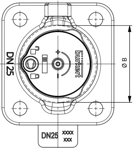
The manual actuator for diaphragm size 25 belongs to size group S (handwheel diameter ∅ B = 45 mm):
| Diaphragm Size | H1 (Open) [mm] | H2 (Open with Stroke Limiter) [mm] | H3 (Closed) [mm] | H4 (Closed with Stroke Limiter) [mm] | ∅ B [mm] |
|---|---|---|---|---|---|
| 15 | 127 | 133 | 121 | 127 | 45 |
| 20 | 138 | 144 | 129 | 135 | 45 |
| 25 | 143 | 149 | 133 | 139 | 45 |
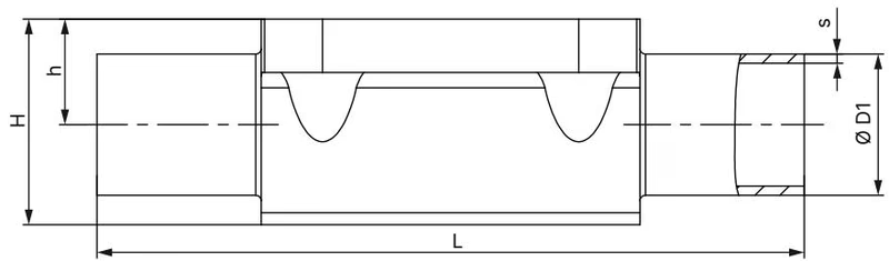
Article 20136039 utilizes SMS 3008 welded port connections in diaphragm size 25 (product code SA60):
| Diaphragm Size | Standard | DN | Pipe ∅D1 [mm] | Wall Thickness s [mm] | Length L [mm] | Port Height h [mm] | Total Height H [mm] | Product Key |
|---|---|---|---|---|---|---|---|---|
| 25 | SMS 3008 | 25 | 25.0 | 1.20 | 129 | 19.0 | 37.0 | SA60 |
| 40 | SMS 3008 | 40 | 38.0 | 1.20 | 161 | 27.6 | 52.4 | SA62 |
| 50 | SMS 3008 | 50 | 51.0 | 1.20 | 192 | 35.5 | 68.3 | SA63 |
| 25 | ISO 1127 / 11866 B | 25 | 33.7 | 2.00 | 129 | 19.0 | 37.0 | SA44 |
| 25 | DIN 11850-2 / 11866 A | 25 | 29.0 | 1.50 | 129 | 19.0 | 37.0 | SD44 |
| 25 | ASME BPE / 11866 C | 1" | 25.4 | 1.65 | 127 | 19.0 | 37.0 | SODF |
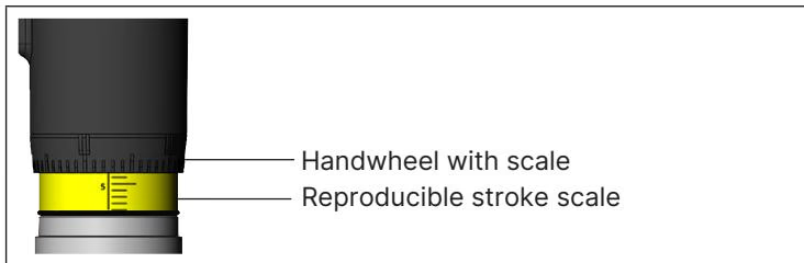
The FullFunction manual actuator incorporates a yellow visual position indicator positioned below the handwheel. When turning the handwheel counterclockwise to open the valve, the indicator and its graduation scale become visible. The handwheel rim carries 50 discrete rotary division marks. Combining the handwheel scale with the stationary stroke scale allows precise and repeatable throttle settings.
Operating Closure Torque
Always close the handwheel manually without wrenches or levers. Stop turning once tight shut-off is achieved. For diaphragm size 25 with an Advanced PTFE diaphragm, static isolation at 10 bar requires a closing torque of 3.5 Nm (+10% tolerance), while closing against full dynamic flow requires 5.0 Nm. Excessive manual force degrades the PTFE sealing lip and shortens diaphragm working life.
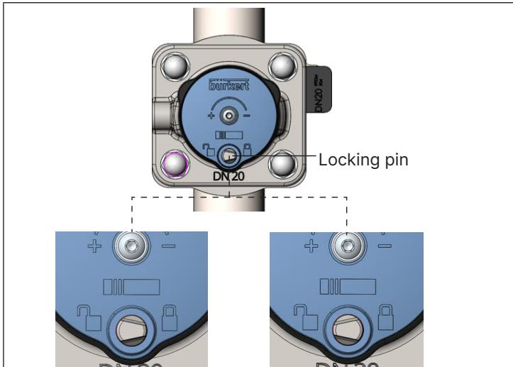
On Type 297x actuators, minimum and maximum stroke limits can be set using an internal adjusting sleeve:
The FullFunction actuator accepts an integrated lockout mechanism. For diaphragm size 25, the locking device offers 12 locking positions per complete handwheel revolution (every 30° rotation, corresponding to 0.15 mm axial stroke increment). Pushing down the locking pin and rotating it 180° engages the spindle. The exposed 3.8 mm cross-bore accommodates a safety padlock to prevent unauthorized repositioning.
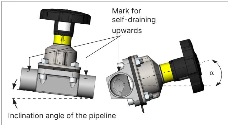
The preferred valve orientation is upright with the actuator positioned vertically upward. Self-draining installation requires setting the pipeline and valve body to the specific drainage angle α permanently marked on the forged body.
Dismantle Before Welding
Thermal conduction from orbital or manual tube welding will destroy the Advanced PTFE/EPDM diaphragm and spindle mechanics. Open the handwheel fully, loosen the body screws crosswise, and detach the actuator and diaphragm subassembly from the forged body prior to welding the SMS 3008 pipe connections.
After orbital or manual welding of the body spigots:
| Diaphragm Size | Body Material | Elastomer Diaphragm (EPDM / FKM) | PTFE / Advanced PTFE (EU) / GYLON® |
|---|---|---|---|
| 15 | VS, VG, Plastics | 3.5 Nm | 4.0 Nm |
| 20 | VS, VG, Plastics | 4.0 Nm | 4.5 Nm |
| 25 | Forged Steel (VS) | 5.0 Nm | 6.0 Nm |
| 32 | VS, VG, Plastics | 6.0 Nm | 8.0 Nm |
| 40 | VS, VG, Plastics | 8.0 Nm | 10.0 Nm |
| 50 | VS, VG, Plastics | 12.0 Nm | 15.0 Nm |
A tolerance of +10% applies to all tightening torques. Retighten the body screws crosswise following the first complete steam SIP cycle.
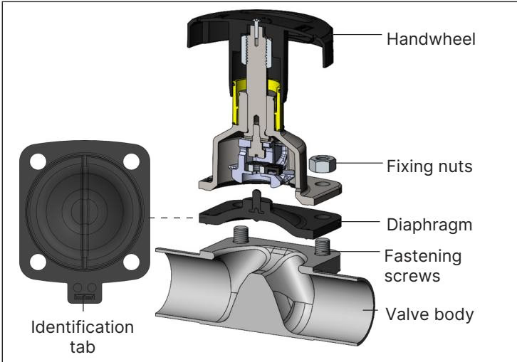
Diaphragm size 25 uses a bayonet catch mechanism for Advanced PTFE diaphragms (Bürkert spare part article 20093082, material designation EPDM E04 / PTFE P06):
Diaphragm Compatibility
If replacing an EPDM diaphragm (threaded connection) with an Advanced PTFE diaphragm on size 25, the threaded compressor insert must be removed before mounting the bayonet pin. Failure to remove the threaded insert will cause severe mechanical damage to the compressor and diaphragm.
Under variable code PX51, Type 2973 is certified as mechanical equipment Category 2G/2D for zones 1/21 and 2/22 pursuant to EPS 18 ATEX 2 008 X and IECEx EPS 18.0007X (Ex h IIC T4...T2 Gb / Ex h IIIC T135°C...T300°C Db).
| Temperature Class | Maximum Surface Temperature | Permissible Ambient Temperature | Maximum Permissible Medium Temperature |
|---|---|---|---|
| T4 | +135 °C | -40 °C to +100 °C | +125 °C |
| T3 | +200 °C | -40 °C to +130 °C | +185 °C |
| T2 | +300 °C | -40 °C to +130 °C | +285 °C |
Electrostatic Discharge Hazard in Ex Zones
Electrostatic charging can create an ignition hazard in potentially explosive atmospheres:
Explore similar products in our catalog