

PN16

BURKERT 333699 (Type 6213 EV) is a servo-assisted 2/2-way diaphragm valve with DN 25 orifice, NPT 1 female port, stainless steel body, EPDM seal, and 230-240 V AC Kick and Drop energy-saving coil.
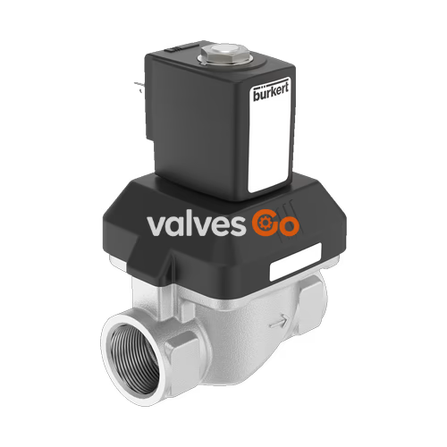
BURKERT 333699 (Type 6213 EV) is a servo-assisted 2/2-way diaphragm valve with spring coupling that allows the main valve orifice to open without requiring an operating differential pressure. Built with a cast stainless steel 1.4408 body, an internal NPT 1 process thread, and EPDM seat and external seals, the valve delivers an open water flow factor (Kv) of 11 m³/h and a gas flow factor (QNn) of 11,900 l/min across an operating pressure range of 0.00 bar to 10.00 bar.
Operating on 230 V to 240 V AC (50/60 Hz), article 333699 integrates Bürkert Kick and Drop double-coil technology (coil size K, 42 mm width). The electronics provide a high inrush power pulse of 85 W for approximately 500 ms to lift the plunger, subsequently stepping down to a cold holding power of 8.5 W and a warm holding power of 7 W, reducing thermal dissipation and electrical power consumption during steady-state operation.
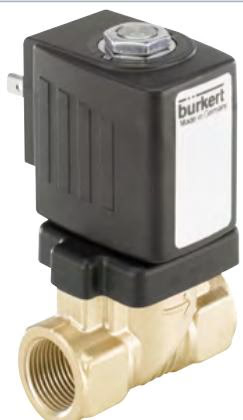
Article 333699 operates in circuit function A (CF A). It is a servo-controlled, 2/2-way valve that remains closed when de-energized (normally closed, P/NC inlet port 1).
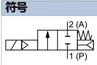
| Circuit Function Symbol | Description |
|---|---|
| CF A | 2/2-way solenoid valve, servo-controlled, normally closed |
| Parameter | Value |
|---|---|
| Model / Article Number | Type 6213 EV / 333699 |
| Circuit Function | A (Normally Closed, 2/2-way) |
| Nominal Diameter (DN) | DN 25 (25.00 mm / 1 inch) |
| Port Connection | Female thread NPT 1 (F2 = 16.8 mm) |
| Installation Length | 95 mm |
| Operating Pressure Range | 0.00 bar - 10.00 bar (PN 10) |
| Water Flow Capacity (Kv) | 11 m³/h (measured at +20 °C, 1 bar inlet pressure, free outlet) |
| Gas Flow Capacity (QNn) | 11,900 l/min |
| Pilot Control Orifice | 1.4 mm |
| Body Material | Stainless steel 1.4408 |
| Seal Material | EPDM (seat seal and external seals) |
| Medium Temperature Range | -30 °C to +100 °C (with epoxy coil) |
| Ambient Temperature Range | -40 °C to +55 °C |
| Maximum Media Viscosity | 21 mm²/s |
| Operating Voltage / Frequency | 230 V - 240 V AC, 50/60 Hz (Voltage tolerance ±10%) |
| Actuator / Coil Technology | Kick and Drop double-coil energy saving technology (CZ05) |
| Coil Size / Width | Size K / 42 mm |
| Power Consumption | Inrush (approx. 500 ms): 85 W; Holding cold: 8.5 W; Holding warm: 7 W |
| Duty Cycle | 100% ED continuous operation (max. 6 switching cycles/min for KD coil) |
| Electrical Port Connection | Plug pattern Form A according to DIN EN 175301-803 (plug enclosed) |
| Degree of Protection | IP65 (with properly mounted Type 2518 cable plug), NEMA 4X |
| Approvals | UL Listed (UL 429), cURus Recognized |
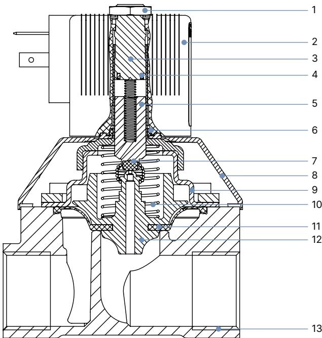
| Item No. | Component | Material |
|---|---|---|
| 1 | Nut | Steel (thick-film passivated acc. to RoHS) / Stainless steel 1.4305, PTFE-coated |
| 2 | Coil | Epoxy (insulation class H) / Polyamide |
| 3 | Stopper | Stainless steel 1.4113 |
| 4 | Shading ring (AC version) | Silver (Ag) with stainless steel body (Copper Cu with brass body) |
| 5 | Magnetic core | Stainless steel 1.4113 |
| 6 | O-ring | FKM |
| 7 | Plunger seal | EPDM (NBR, FKM optional) |
| 8 | Bonnet | PA6 |
| 9 | Cover | Stainless steel 1.4301 (DN 10 to DN 25) |
| 10 | Spring | Stainless steel 1.4310 |
| 11 | Diaphragm | EPDM (NBR, FKM optional) |
| 12 | Diaphragm support | PPS GF40 in combination with stainless steel parts |
| 13 | Valve body | Stainless steel 1.4408 |
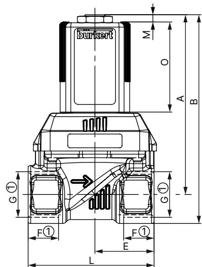
All dimensions are stated in millimeters (mm). For NPT threads, thread depth F2 and thread marking G 2 apply.
| DN | A | B | C | D | E | F1 (G) | G 1 | F2 (NPT) | G 2 | F3 (Rc) | G 3 | L | SW | Coil Size |
|---|---|---|---|---|---|---|---|---|---|---|---|---|---|---|
| 10 | 71.1 | 82.1 | 36 | 46 | 22 | 12 | G 1/4 | 10.0 | NPT 1/4 | — | — | 50 | 22 | 5 and 6 |
| 10 | 71.1 | 82.1 | 36 | 46 | 22 | 12 | G 3/8 | 10.3 | NPT 3/8 | 10.1 | Rc 3/8 | 50 | 22 | 5 and 6 |
| 10 | 73.1 | 86.6 | 36 | 46 | 24.5 | 14 | G 1/2 | 13.7 | NPT 1/2 | 13.2 | Rc 1/2 | 55 | 27 | 5 and 6 |
| 13 | 82.6 | 95.9 | 44.5 | 56.7 | 32.5 | 14 | G 1/2 | 13.7 | NPT 1/2 | 13.2 | Rc 1/2 | 65 | 27 | 5 and 6 |
| 13 | 84.6 | 100.6 | 44.5 | 56.7 | 32.5 | 16 | G 3/4 | 14.0 | NPT 3/4 | 14.5 | Rc 3/4 | 65 | 32 | 5 and 6 |
| 20 | 97.1 | 113.1 | 65 | 76.6 | 37 | 16 | G 3/4 | 14.0 | NPT 3/4 | 14.5 | Rc 3/4 | 80 | 32 | 5 and 6 |
| 20 | 99.6 | 120.1 | 65 | 76.6 | 37.5 | 18 | G 1 | 16.8 | NPT 1 | 16.8 | Rc 1 | 80 | 41 | 5 and 6 |
| 13 | 109.3 | 122.8 | 44.5 | 56 | 32.5 | 14 | G 1/2 | 13.7 | NPT 1/2 | 13.2 | Rc 1/2 | 65 | 27 | K and L |
| 13 | 111.3 | 127.3 | 44.5 | 56 | 32.5 | 16 | G 3/4 | 14.0 | NPT 3/4 | 14.5 | Rc 3/4 | 65 | 32 | K and L |
| 20 | 123.9 | 139.9 | 65 | 76.6 | 37 | 16 | G 3/4 | 14.0 | NPT 3/4 | 14.5 | Rc 3/4 | 80 | 32 | K and L |
| 20 | 126.4 | 146.9 | 65 | 76.6 | 37.5 | 18 | G 1 | 16.8 | NPT 1 | 16.8 | Rc 1 | 80 | 41 | K and L |
| 25 | 143.4 | 163.4 | 77 | 88 | 46 | 18 | G 1 | 16.8 | NPT 1 | 16.8 | Rc 1 | 95 | 41 | K and L |
| 25 | 148.3 | 173.3 | 77 | 88 | 46 | 20 | G 1 1/4 | 17.3 | NPT 1 1/4 | 19.1 | Rc 1 1/4 | 95 | 50 | K and L |
| 40 | 159.4 | 189.4 | 104.5 | 117 | 61 | 22 | G 1 1/2 | 17.3 | NPT 1 1/2 | 19.1 | Rc 1 1/2 | 126 | 60 | K and L |
| 40 | 165.4 | 200.4 | 104.5 | 117 | 64 | 24 | G 2 | 17.6 | NPT 2 | 23.4 | Rc 2 | 132 | 70 | K and L |
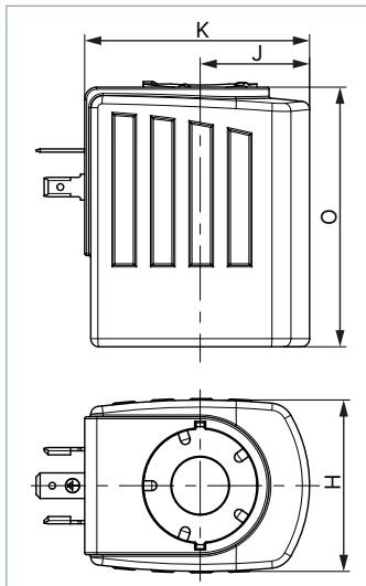
| Coil Size | H (mm) | J (mm) | K (mm) | O (mm) | M (mm) |
|---|---|---|---|---|---|
| 5 | 32 | 20.5 | 45 | 41 | 3.4 |
| 6 | 40 | 23.5 | 51 | 41 | 3.4 |
| K | 42 | 27.0 | 55.5 | 64 | 7.0 |
| L | 65 | 37.5 | 72 | 64 | 7.0 |
Article 333699 utilizes a double-coil actuator with integrated electronics (CZ05) for high opening force followed by low holding energy dissipation.
| Orifice DN (mm) | Coil Size (mm) | Coil Code | Cold Inrush Power (approx. 500 ms) | Cold Holding Power | Warm Holding Power |
|---|---|---|---|---|---|
| 10 - 13 | 40 | 6 | 20 W | 2.0 W | — |
| 13 - 20 | 42 | K | 44 W | 6.5 W | 5.5 W |
| 13 - 20 (ATEX) | 42 | K | 44 W | 6.5 W | 5.5 W |
| 13 - 40 (DN 25) | 42 | K | 85 W | 8.5 W | 7.0 W |
Switching Frequency and Duty Cycle
Unless specified otherwise, the solenoid actuator is rated for 100% ED continuous operation. When using Kick and Drop coils, the maximum permissible operating frequency is 6 switching cycles per minute.
Before connecting the valve into the system, clear all piping of chips, rust, and particulate contamination.
Upstream Filtration Recommendation
Install a dirt trap or strainer with a mesh rating of ≤ 500 µm upstream of the valve inlet to prevent particulate matter from lodging in the pilot channels or clogging the diaphragm control hole.
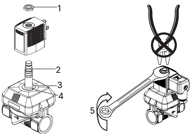
| Item | Description |
|---|---|
| 1 | Fastening nut |
| 2 | Core guide tube |
| 3 | O-ring |
| 4 | Anti-twist device |
| 5 | Tightening torque for fixing nut |
When servicing or replacing the solenoid coil, position the coil housing over the core guide tube and anti-twist device, then tighten the retaining nut using an open-end wrench.
| Solenoid Type | Solenoid Width | Fastening Nut Tightening Torque |
|---|---|---|
| AC10 | 32 mm or 40 mm | 5 Nm |
| AC19 (Size K) | 42 mm | 10 Nm |
Operating Safety Warnings
Explore similar products in our catalog


