


PN16

TLV J3S-X-BV stainless steel free float steam trap with built-in bypass blowdown ball valve and X-element air vent. Max operating pressure 1.0 MPaG, max temp 185°C.
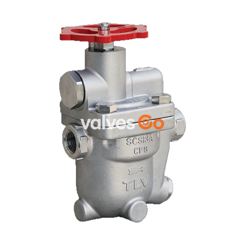
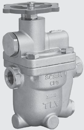
The TLV J3S-X-BV is a reliable and durable stainless steel free float steam trap that includes a built-in bypass valve to facilitate the discharge of large quantities of condensate produced at start-up by process equipment, heaters, air conditioners, and tank heating. The tight-sealing manually operated ball valve incorporated into the cover can be used for bypass blowdown to significantly reduce start-up times.
This revolutionary design employs a high-performance thermostatic capsule (X-element) as an air vent with a "fail open" feature that vents air automatically until close-to-steam temperature. The self-modulating precision-ground free float provides continuous, smooth, low-velocity condensate discharge as process loads vary, ensuring a steam-tight seal even under no-load conditions.
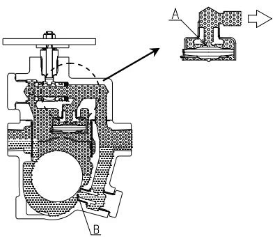
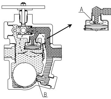
1. Initial Air and Cold Condensate Discharge At startup, before steam is supplied, the trap is cold so the X-element is contracted and the air vent valve seat is open. This allows for the rapid discharge of air through the air vent valve and cold condensate through the orifice. Initial air/condensate can be discharged rapidly using the bypass blowdown valve as necessary.
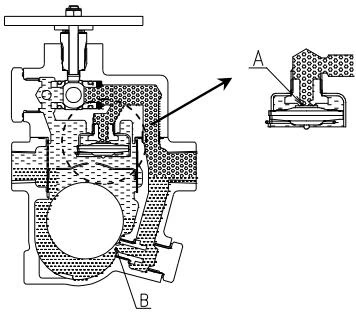
2. Condensate Discharge After the discharge of initial air and cold condensate (bypass blowdown valve closed), the heat of the inflowing steam and condensate causes the X-element to expand, closing the air vent valve. The rising condensate level causes the float to rise due to buoyancy, opening the orifice and allowing condensate to be discharged.
3. Hot Air Discharge Should hot air flow into the trap with the steam during normal operation, the temperature of the X-element drops, causing it to momentarily contract and open the air vent valve, which allows for the rapid discharge of the air. After the air is discharged and steam contacts the X-element, the temperature will increase causing the air vent valve to close.
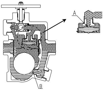
4. Closed Position When the condensate flow rate decreases, the float falls as condensate is discharged, closing off the orifice. A water seal is maintained at all times over the orifice to prevent steam loss. The high steam temperature causes the X-element to expand, keeping the air vent closed.
| Model | J3S-X-BV |
|---|---|
| Connection | Screwed, Flanged |
| Size | 1/2", 3/4", 1" (DN 15, 20, 25) |
| Orifice No. | 2, 5, 10 |
| Maximum Operating Pressure (PMO) | 0.2, 0.5, 1.0 MPaG (2, 5, 10 barg) |
| Maximum Differential Pressure (ΔPMX) | 0.2, 0.5, 1.0 MPa (2, 5, 10 bar) |
| Maximum Operating Temperature (TMO) | 185 °C |
| Subcooling of X-element Fill | Up to 6 °C |
| Type of X-element | C6 |
PRESSURE SHELL DESIGN CONDITIONS
Maximum Allowable Pressure (PMA): 10 barg (1.0 MPaG) Maximum Allowable Temperature (TMA): 185 °C These are design conditions, NOT operating conditions. Do not use this product outside the recommended operating pressure, temperature, and other specification ranges.
In addition to the manual J3S-X-BV, the series includes automated bypass models:
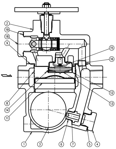
| Description | Material | ASTM/AISI |
|---|---|---|
| Body | Cast Stainless Steel | A351/A351M Gr.CF8 |
| Cover | Cast Stainless Steel | A351/A351M Gr.CF8 |
| Float | Stainless Steel | AISI316L |
| Orifice Plug | Cast Stainless Steel | A351/A351M Gr.CF8 |
| Screen inside/outside | Stainless Steel | AISI430/304 |
| Cover Gasket | Fluorine Resin | PTFE |
| X-element | Stainless Steel | - |
| Air Vent Valve Seat | Stainless Steel | AISI420F |
| Ball | Stainless Steel | AISI304 |
| Inlet/Outlet Valve Seat | Fluorine Resin w/ Graphite | PTFE |
| O-Ring | Fluorine Rubber | D2000HK |
| Gland Packing | Fluorine Resin w/ Carbon | PTFE |
J3S-X-BV Screwed
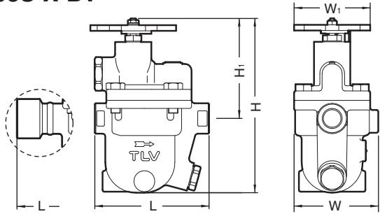
| Size | L (mm) | H (mm) | H1 (mm) | W (mm) | W1 (mm) | Weight (kg) |
|---|---|---|---|---|---|---|
| 1/2" | 120 | 183 | 105 | 89.5 | 90 | 3.0 |
| 3/4" | 190 | 183 | 105 | 89.5 | 90 | 3.5 |
| 1" | 200 | 183 | 105 | 89.5 | 90 | 3.7 |
J3S-X-BV Flanged
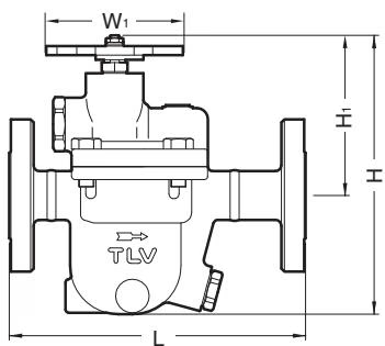
| DN | L (DIN PN16) | L (ASME 150RF) | L (ASME 300RF) | H (mm) | H1 (mm) | W1 (mm) | Weight (kg) |
|---|---|---|---|---|---|---|---|
| 15 | 170 | 175 | 175 | 183 | 105 | 90 | 4.0 |
| 20 | 170 | 195 | 195 | 183 | 105 | 90 | 4.4 |
| 25 | 180 | 215 | 219 | 183 | 105 | 90 | 5.7 |
Bypass Valve Usage
The built-in bypass valve cannot be used as a stop valve for the inlet and outlet of the product. It is recommended that a separate stop valve be installed at the inlet and outlet for maintenance purposes.
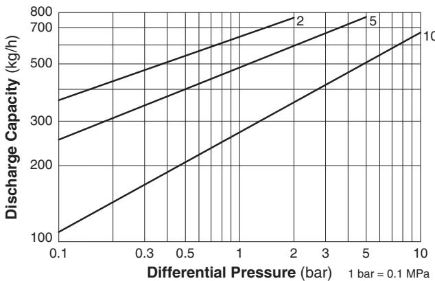
Discharge Capacity (Steam Trap)
Bypass Capacity (Ball Valve)
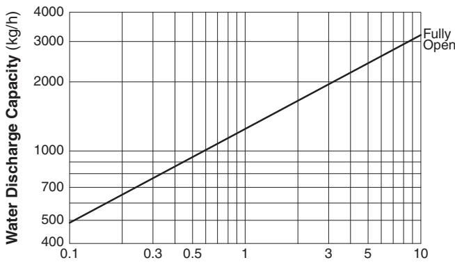
Valve Operation
Operate the bypass valve (ball valve) in only the fully open or fully closed positions. Operation in an intermediate position will damage the valve seat and may lead to leaking of the valve.




