

PN16
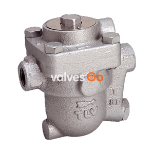
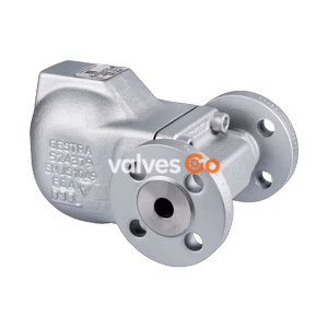
TLV J3S-X S1/S2 cast stainless steel free float steam traps with thermostatic air venting, designed for rubber vulcanizers up to 1.4 MPaG (14 barg).
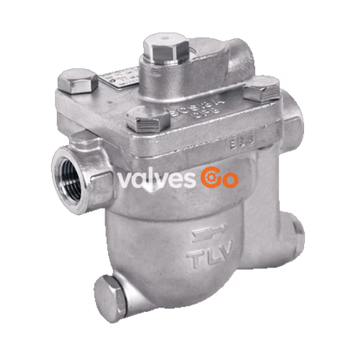
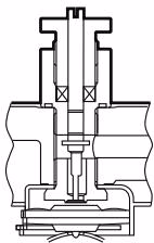
The TLV J3S-X S1 and J3S-X S2 are cast stainless steel free float steam traps with thermostatic air venting (X-element), designed especially for use in rubber vulcanizer applications up to 1.4 MPaG (14 barg). They feature a cover plug for retrofitting a lock release valve against steam locking, a drain plug for installing a blowdown valve, and an internal screen with (S2) or without (S1) wire mesh. The traps discharge condensate continuously and automatically at a temperature slightly lower than saturation.
| Model | J3S-X S1 | J3S-X S2 |
|---|---|---|
| Connection | Screwed, Flanged | Screwed, Flanged |
| Size (Screwed) | 1/2", 3/4", 1" | 1/2", 3/4", 1" |
| Size (Flanged) | DN 15, 20, 25 | DN 15, 20, 25 |
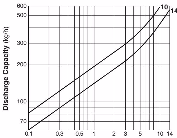
| Orifice No. | 10, 14 | 10, 14 |
| Max Operating Pressure (PMO) | 1.0, 1.4 MPaG | 1.0, 1.4 MPaG |
| Max Differential Pressure (ΔPMX) | 1.0, 1.4 MPa | 1.0, 1.4 MPa |
| Max Operating Temperature (TMO) | 220 °C | 220 °C |
| Subcooling of X-element | up to 11 °C | up to 11 °C |
| Type of X-element | C11 | C11 |
| Internal Screen | φ1.2 mm punched hole (16 mesh eq.) | φ1.2 mm punched hole + wire mesh (60 mesh) |
PRESSURE SHELL DESIGN CONDITIONS
(NOT OPERATING CONDITIONS):
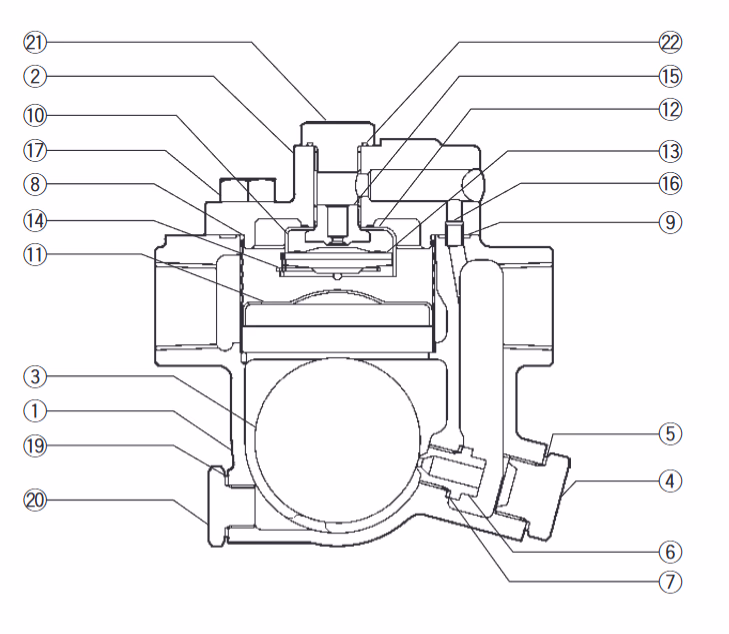
| No. | Description | Material | DIN / ASTM |
|---|---|---|---|
| 1 | Body | Cast Stainless Steel | 1.4312 / A351 Gr.CF8 |
| 2 | Cover | Cast Stainless Steel | 1.4312 / A351 Gr.CF8 |
| 3 | Float | Stainless Steel | 1.4404 / AISI 316L |
| 4 | Orifice Plug | Cast Stainless Steel | 1.4312 / A351 Gr.CF8 |
| 6 | Orifice | - | - |
| 8 | Screen | Stainless Steel | 1.4016, 1.4301 / AISI 430, 304 |
| 9 | Cover Gasket | Fluorine Resin PTFE | PTFE |
| 13 | X-element | Stainless Steel | - |
| 20 | Drain Plug | Stainless Steel | 1.4305 / AISI 303 |
| 21 | Cover Plug | Stainless Steel | 1.4305 / AISI 303 |
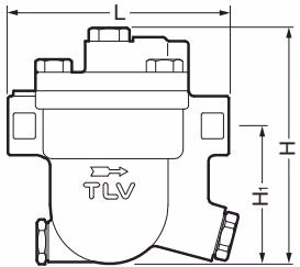
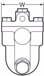
| Size | L (mm) | H (mm) | H1 (mm) | W (mm) | Weight (kg) |
|---|---|---|---|---|---|
| 1/2" | 120 | 130 | 75 | 80 | 2.5 |
| 3/4" | 120 | 130 | 72.5 | 80 | 2.6 |
| 1" | 120 | 137 | 75 | 80 | 2.8 |
| DN | L (DIN PN25/40) | H (mm) | H1 (mm) | Weight (kg) |
|---|---|---|---|---|
| 15 | 150 | 132 | 84 | 3.4 |
| 20 | 150 | 140 | 90 | 3.6 |
| 25 | 160 | 147 | 92 | 4.6 |
DANGER
DO NOT use this product under conditions that exceed maximum differential pressure, as condensate backup will occur!
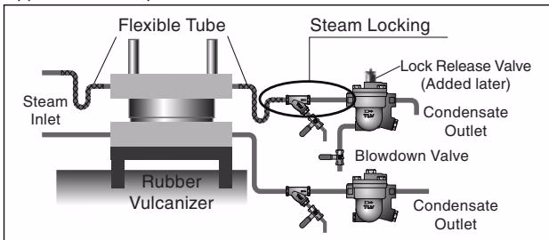
In steam-using rubber vulcanizers, the heat plate moves up and down making it easy for steam locking to occur. This can result in condensate backup, which causes temperature drops.
The S series has a plug in the cover that can be removed to allow an LR3 lock release valve to be installed for combating steam locking. By opening the valve a tiny amount to release "locked" steam, the proper temperature can be ensured.
A drain plug at the bottom of the body is equipped as standard. By removing the plug and installing a manual or automatic valve, condensate blowdown can be carried out when there is a temperature drop. (Note: Since the thread standard is G 1/4, a thread conversion fitting is needed for piping).
Install the steam trap within the allowable inclination, as shown below. Also make sure that the arrow mark on the body corresponds with the direction of flow.

Operational inspections should be performed at least twice per year, or as called for by trap operating conditions.
| Condition | Description |
|---|---|
| Normal | Condensate is discharged continuously with flash steam and the sound of flow can be heard. |
| Blocked | No condensate is discharged. The trap is quiet and makes no noise, and surface temperature is low. |
| Blowing | Live steam continually flows from the outlet and there is a continuous metallic sound. |
| Steam Leakage | Live steam is discharged through the trap outlet together with the condensate and there is a high-pitched sound. |
| Problem | Cause | Remedy |
|---|---|---|
| No condensate is discharged (blocked) | Float is damaged or filled with condensate Orifice, screen or piping is clogged Steam-locking has occurred X-element is damaged | Replace the float Clean Blowdown through bypass or close inlet to cool trap Replace the X-element |
| Steam is discharged or leaks (blowing) | Rust and scale accumulated around orifice or under float Orifice is damaged Float is deformed or coated with scale Trap installed above maximum inclination | Clean Replace the orifice Clean or replace the float Correct the installation |