Repairable

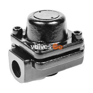
TLV LV21 all-stainless steel balanced pressure thermostatic steam trap with fail-open design. Suitable for tracing, vessels, and heaters up to 2.1 MPaG.
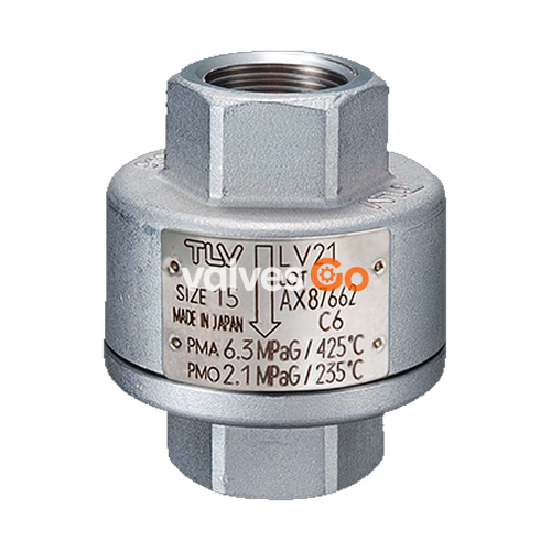
The TLV LV21 is an all-stainless steel balanced pressure thermostatic steam trap designed for applications where the condensate load is relatively small, such as tracing lines, vessels, and heaters. It features a revolutionary "fail open" design and utilizes a high-performance X-element that responds highly sensitively to temperature changes, discharging air and large quantities of condensate immediately upon startup to significantly reduce startup time.
Preferably installed vertically, the LV21 offers a rugged yet light construction capable of withstanding superheat and water hammer. Its cyclic operation maintains fixed subcooling throughout the entire pressure range, ensuring outstanding air venting capability and preventing air binding.
| Parameter | Value |
|---|---|
| Connection | Screwed (BSP DIN 2999, other standards available) |
| Size | 1/4", 3/8", 1/2" |
| Max. Operating Pressure (PMO) | 21 barg (2.1 MPaG) |
| Min. Operating Pressure | 0.1 barg (0.01 MPaG) |
| Maximum Back Pressure | 90% of Inlet Pressure |
| Subcooling of X-element Fill | up to 6 °C (option: up to 22 °C) |
| Type of X-element | C6 (option: C22) |
PRESSURE SHELL DESIGN CONDITIONS
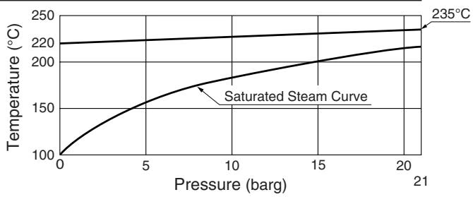
Maximum Allowable Pressure (PMA): 63 barg (6.3 MPaG) Maximum Allowable Temperature (TMA): 425 °C Minimum Allowable Temperature: -40 °C These are design conditions, NOT operating conditions. Do not use this product outside of the specification range.
| No. | Description | Material | DIN* | ASTM/AISI* |
|---|---|---|---|---|
| ① | Body Upper Part | Cast Stainless Steel A351/A351M Gr.CF8 or CF8M | 1.4312 or 1.4410 | - |
| ② | Body Lower Part | Cast Stainless Steel A351/A351M Gr.CF8 or CF8M | 1.4312 or 1.4410 | - |
| ③ | X-element | Stainless Steel | - | - |
| ④ | Valve Seat | Stainless Steel SUS630 | 1.4542 | AISI630 |
| ⑤ | Screen | Stainless Steel SUS304 | 1.4301 | AISI304 |
| ⑥ | Nameplate | Stainless Steel SUS304/SUS316L | 1.4301/1.4404 | AISI304/AISI316L |
| ⑦ | Spring Clip | Stainless Steel SUS304 | 1.4301 | AISI304 |
*Equivalent materials
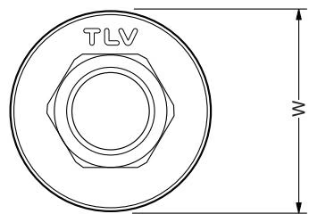
| Size | L (mm) | φW (mm) | Weight (kg) |
|---|---|---|---|
| 1/4" | 55 | 47 | 0.4 |
| 3/8" | 55 | 47 | 0.4 |
| 1/2" | 55 | 47 | 0.4 |
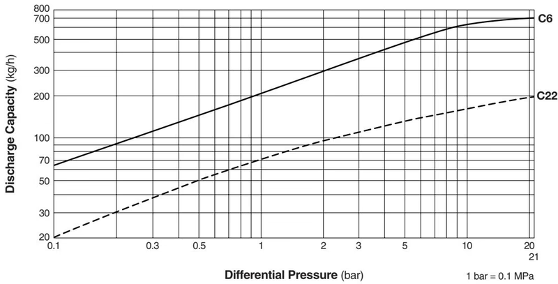
Capacity Notes
Safety Considerations
Take measures to prevent people from coming into direct contact with product outlets. Failure to do so may result in burns or other injury from the discharge of fluids.
Operational inspections should be performed at least twice per year, or as called for by trap operating conditions. Faulty steam traps may result in losses due to steam leakage.
WARNING
Before attempting to open the trap, close the inlet and outlet isolation valves and wait until the trap has cooled to room temperature. Failure to do so may result in burns or injury.
A visual inspection can be carried out to aid in determining the necessity for immediate maintenance or repair if the trap is open to atmosphere.
| Part | Disassembly | Reassembly |
|---|---|---|
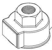
| Cover | Use an open-end wrench to remove | Clean seating surfaces; coat threaded portions with anti-seize; tighten to 120 N·m (88 lbf·ft) |
| Spring Clip | Use pliers to remove | Insert securely into the 3 slots in the guide or cover |
| X-element | Use pliers to grasp the ball at the tip of the element and remove | Insert with right side up; make sure it does not catch on guide or cover |
| Screen | Be careful not to bend the screen | Be careful not to bend the screen |
If the expected performance is unachievable after installation, check the following:
| Problem | Cause | Remedy |
|---|---|---|
| No condensate is discharged (blocked) or discharge is poor | X-element is stuck to the valve seat | Clean |
| Valve seat is clogged | Clean | |
| Screen is clogged with rust or scale | Clean | |
| Steam-locking has occurred | Perform a bypass blowdown, or close the trap inlet valve and allow the trap to cool. Piping correction may also be required. | |
| Trap operating pressure exceeds maximum specified operating pressure | Study inlet pressure | |
| Differential pressure is insufficient | Study inlet / outlet pressure | |
| Steam leakage or blow-off | Valve closure is obstructed by rust, etc. | Clean (inspect screen as well) |
| X-element is worn or damaged | Replace X-element | |
| Valve seat is worn or damaged | Replace cover (valve seat is pressed in the cover) | |
| Improper installation | Correct the installation | |
| Severe vibration of trap | Reinforce trap piping supports | |
| Leakage from other location | Cover is loose or gasket is worn or damaged | Tighten cover or replace gasket |
Explore similar products in our catalog