


PN16

TLV SJ7FNX and SJ7FVX ductile cast iron free float steam traps with three-point seating and thermostatic air venting for medium-size process equipment.
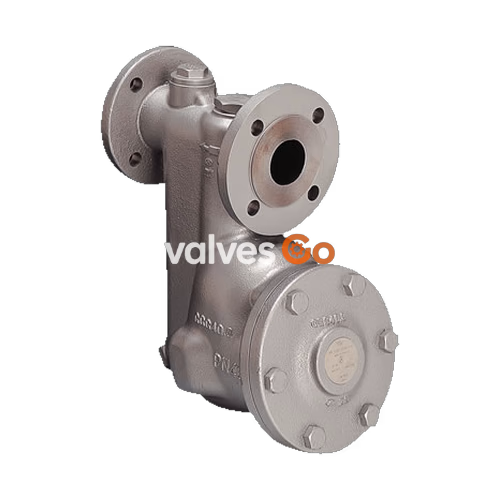
The TLV SJ7FNX and SJ7FVX are ductile cast iron free float steam traps with three-point seating and thermostatic air venting (X-element). They are reliable and durable steam traps with tight shut-off, designed for use on medium-size process equipment such as heat exchangers, tank heaters, dryers, and process equipment. The SJ7FNX is designed for horizontal piping installation, while the SJ7FVX is designed for vertical piping installation.
These inline repairable traps discharge condensate continuously and automatically at a temperature slightly lower than saturation temperature. The self-modulating free float provides continuous, smooth, low-velocity condensate discharge as process loads vary. A precision-ground float, constant water seal, and three-point seating design ensure a steam-tight seal, even under no-load conditions. The thermostatic capsule (X-element) with a "fail open" feature vents air automatically until close-to-steam temperature. A built-in screen with a large surface area ensures extended trouble-free operation, and easy inline access to internal parts simplifies cleaning and reduces maintenance costs.
| Model | SJ7FNX | SJ7FVX |
|---|---|---|
| Installation | Horizontal | Vertical |
| Connection | Flanged | Flanged |
| Size | DN 40, 50 | DN 40, 50 |
| Orifice No. | 2, 5, 9, 14, 22 | 2, 5, 9, 14, 22 |
| Maximum Operating Pressure (PMO) | 2, 5, 9, 14, 22 barg | 2, 5, 9, 14, 22 barg |
| Maximum Differential Pressure (ΔPMX) | 2, 5, 9, 14, 22 bar | 2, 5, 9, 14, 22 bar |
| Maximum Operating Temperature (TMO) | 220 °C | 220 °C |
| Subcooling of X-element Fill | up to 6 °C | up to 6 °C |
| Type of X-element | C6 | C6 |
WARNING
PRESSURE SHELL DESIGN CONDITIONS (NOT OPERATING CONDITIONS):
To avoid abnormal operation, accidents or serious injury, DO NOT use this product outside of the specification range. Local regulations may restrict the use of this product to below the conditions quoted.
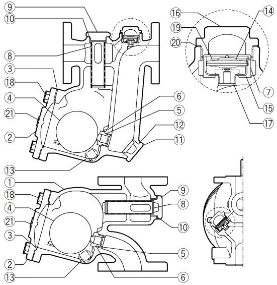
| No. | Description | Material | DIN | ASTM/AISI |
|---|---|---|---|---|
| 1 | Body | Ductile Cast Iron GGG40.3/EN 5.3103 | 0.7043 | A395 Gr.60-40-18 |
| 2 | Cover | Ductile Cast Iron GGG40.3/EN 5.3103 | 0.7043 | A395 Gr.60-40-18 |
| 3 | Cover Gasket | Fluorine Resin PTFE | PTFE | PTFE |
| 4 | Float | Stainless Steel SUS316L | 1.4404 | AISI 316L |
| 5 | Orifice | - | - | - |
| 6 | Orifice Gasket | Fluorine Resin PTFE | PTFE | PTFE |
| 7 | X-element Screen | Stainless Steel SUS304 | 1.4301 | AISI 304 |
| 8 | Screen | Stainless Steel SUS430 | 1.4016 | AISI 430 |
| 9 | Screen Holder | Cast Stainless Steel A351 Gr.CF8 | 1.4312 | - |
| 10 | Screen Holder Gasket | Soft Iron SUYP | 1.1121 | AISI 1010 |
| 11 | Orifice Plug (SJ7FNX) | Cast Stainless Steel A351 Gr.CF8 | 1.4312 | - |
| 12 | Orifice Plug Gasket (SJ7FNX) | Soft Iron SUYP | 1.1121 | AISI 1010 |
| 13 | Drain Plug | Carbon Steel SS400 | 1.0037 | A6 |
| 14 | X-element | Stainless Steel | - | - |
| 15 | X-element Guide | Stainless Steel SUS304 | 1.4301 | AISI 304 |
| 16 | X-element Cover | Cast Stainless Steel A351 Gr.CF8 | 1.4312 | - |
| 17 | Air Vent Valve Seat | Stainless Steel SUS420F | 1.4028 | AISI 420F |
| 18 | Cover Bolt | Carbon Steel S45C | 1.0503 | AISI 1045 |
| 19 | Spring Clip | Stainless Steel SUS304 | 1.4301 | AISI 304 |
| 20 | X-element Cover Gasket | Fluorine Resin PTFE | PTFE | PTFE |
| 21 | Nameplate | Stainless Steel SUS304 | 1.4301 | AISI 304 |
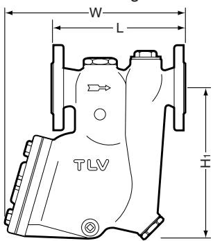
| DN | L (DIN 2501 PN25/40) | H1 | W | B | Weight (kg) |
|---|---|---|---|---|---|
| 40 | 230 mm | 312 mm | 346 mm | 205 mm | 26 |
| 50 | 230 mm | 312 mm | 346 mm | 205 mm | 28 |
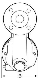
| DN | L (DIN 2501 PN25/40) | W1 | B | Weight (kg) |
|---|---|---|---|---|
| 40 | 230 mm | 304 mm | 205 mm | 22 |
| 50 | 230 mm | 304 mm | 205 mm | 23 |
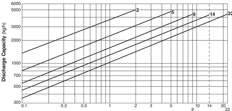
INFO
WARNING
DO NOT use this product under conditions that exceed maximum differential pressure, as condensate backup will occur!
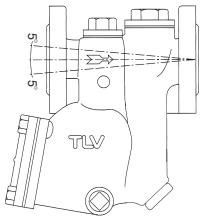
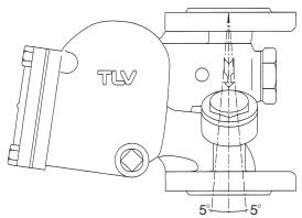
| Requirement | Correct | Incorrect |
|---|---|---|
| Install a catchpot with the proper diameter. | Diameter is adequate. | Diameter is too small. |
| Make sure the flow of condensate is not obstructed. | Flow is clear. | Diameter is too small and inlet protrudes into pipe. |
| To prevent rust and scale from flowing into the trap, connect the inlet pipe 25 - 50 mm (1 - 2 in) above the base of the T - pipe. | Connected above base. | Rust and scale flow into the trap with the condensate. |
| When installing on the blind end, make sure nothing obstructs the flow of condensate. | Flow is clear. | Condensate collects in the pipe. |
Operational inspections should be performed at least twice per year, or as called for by trap operating conditions. Steam trap failure may result in temperature drop in the equipment, poor product quality or losses due to steam leakage.
DANGER
NEVER apply direct heat to the float. The float may explode due to increased internal pressure, causing accidents leading to serious injury or property and equipment damage.
| Part | Inspection Item |
|---|---|
| Body, Cover | Check inside for damage, dirt, grease, oil film, rust or scale |
| Gaskets | Check for warping or damage |
| X-element | Check for damage |
| Screen | Check for clogging, corrosion or damage |
| Float | Check for deformation, damage, oil film or water inside |
| Air Vent Valve Seat, Orifice | Check for rust, scale, oil film, wear or damage |
| Part | Torque (N·m) | Distance Across Flats (mm) |
|---|---|---|
| Cover Bolt | 100 | 24 |
| Orifice | 120 | 30 |
| Screen Holder | 400 | 50 |
| Drain Plug | 30 | 12 |
| X-element Cover | 140 | 32 |
| Air Vent Valve Seat | 35 | 19 |
| Orifice Plug | 400 | 50 |
A visual inspection can be carried out to aid in determining the necessity for immediate maintenance or repair, if the trap is open to atmosphere.
| Problem | Cause | Remedy |
|---|---|---|
| No condensate is discharged or discharge is poor | Float is damaged or filled with condensate | Replace the float |
| Orifice, screen or piping is clogged with rust or scale | Clean | |
| Steam-locking has occurred | Blowdown through the bypass or close the trap inlet valve and allow the trap to cool | |
| X-element is damaged | Replace the X-element | |
| The trap operating pressure exceeds the maximum specified pressure, or there is insufficient pressure differential | Compare specifications and actual operating conditions | |
| Steam is discharged or leaks from the trap outlet | Rust and scale have accumulated around the orifice or under the float | Clean |
| Orifice is damaged | Replace the orifice | |
| Float is deformed or coated with scale | Clean or replace the float | |
| Trap is installed above the maximum allowable inclination angle | Correct the installation | |
| Vibration of trap occurs | Lengthen inlet piping, then fasten it securely | |
| The X-element is damaged, or clogged with rust or scale | Clean or replace the X-element | |
| Steam leaks from a place other than the trap outlet | Deterioration of or damage to gaskets | Replace with new gaskets |
| Leakage from eroded cavities of body or cover | Replace the trap | |
| Improper tightening torque for cover was used | Tighten to the proper torque | |
| Float is frequently damaged | Water hammer occurs | Examine the piping for problems that can cause water hammer |
Models SJ7FNB and SJ7FVB feature an integral plate-type bimetal air vent unit.
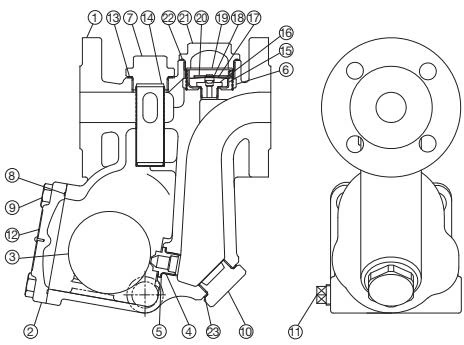
| Part | Disassembly | Reassembly |
|---|---|---|
| Element Cover | Remove with a socket wrench | Consult the table of tightening torques and tighten to the proper torque |
| Element Cover Gasket | Remove the gasket and clean sealing surfaces | Replace with a new gasket |
| Spring Clip | Pinch the insides together and remove from the element guide | Insert it securely into the groove |
| Bimetal Unit | - | Insert the bimetal unit into the element guide with "T" mark on the bimetal facing towards the air vent valve seat. |
| Air Vent Valve Seat (for Bimetal) | Remove with a socket wrench | Consult the table of tightening torques and tighten to the proper torque |
| Part | Torque (N·m) | Distance Across Flats (mm) |
|---|---|---|
| Element Cover | 140 | 32 |
| Air Vent Valve Seat | 35 | 19 |




