PN16
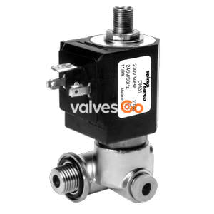
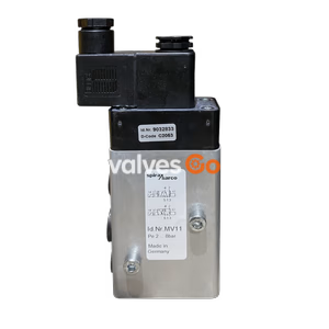
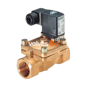
Yoshitake DP-16 diaphragm type pilot-operated solenoid valve. Features stainless steel wetted parts, zero leakage, and horizontal/vertical installation. Handles air, water, and oil up to 1.0 MPa.
Yoshitake DP-16 diaphragm type solenoid valve is a highly reliable ultra-high performance pilot-operated valve. Equipped with stainless steel wetted parts, it ensures outstanding corrosion resistance. The valve provides zero seat leakage and supports both horizontal and vertical installation.
Designed for diverse industrial applications, the DP-16 series effectively handles air, cold and hot water, and oil (20 cSt or less) at working pressures up to 1.0 MPa. The series includes the standard normally closed model (DP-16), a normally opened variant (DP-16C), and DC coil options (DP-16D, DP-16CD) to suit various control requirements.
| Item | Specification |
|---|---|
| Application | Air, Cold and hot water, Oil (20 cSt or less) |
| Working pressure | 0-1.0 MPa (unusable under vacuum) |
| Min. differential pressure | 0 MPa (0.1 MPa or more is required for vertical installation) |
| Valve seat leakage | None (by confirming pressure gauge visually) |
| Max. temperature | 60°C |
| Operation | Normally closed / Normally opened |
| Body Material | Stainless steel |
| Valve Material | NBR (diaphragm) |
| Connection | JIS Rc screwed |
Additional Options
| Rated voltage | AC100/200V, AC110/220V (50/60 Hz) | DC24V |
|---|---|---|
| Allowable regulation | Rated voltage ±10% | Rated voltage ±10% |
| Rated current | 0.42/0.21A (100V/200V), 0.38/0.19A (110V/220V) | 1.13A |
| Starting current | 1.64/0.82A (100V/200V), 1.48/0.74A (110V/220V) | - |
| Insulation type | Class H | Class H |
| Protection structure | Dust-proof, Splash-proof | Dust-proof, Splash-proof |
| Degree of protection | IP64 | IP64 |
| Insulation resistance | More than 50MΩ / 500V megger | More than 50MΩ / 500V megger |
| Anti-voltage test | 1500V/min | 1500V/min |
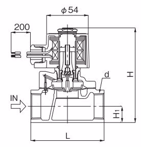
| Nominal size | d | L (mm) | H (mm) | H1 (mm) | Weight (kg) |
|---|---|---|---|---|---|
| 15A | Rc 1/2 | 70 | 109.5 | 14.5 | 1.1 |
| 20A | Rc 3/4 | 80 | 116.5 | 17.5 | 1.3 |
| 25A | Rc 1 | 95 | 123.5 | 21.0 | 1.7 |
| 32A | Rc 1-1/4 | 110 | 150.5 | 26.0 | 2.5 |
| 40A | Rc 1-1/2 | 120 | 157.5 | 29.5 | 3.1 |
| 50A | Rc 2 | 140 | 172.5 | 36.5 | 5.0 |
| Nominal size | d | L (mm) | H (mm) | H1 (mm) | Weight (kg) |
|---|---|---|---|---|---|
| 15A | Rc 1/2 | 70 | 172 | 14.5 | 1.4 |
| 20A | Rc 3/4 | 80 | 179 | 17.5 | 1.6 |
| 25A | Rc 1 | 95 | 186 | 21.0 | 2.0 |
| 32A | Rc 1-1/4 | 110 | 213 | 26.0 | 2.8 |
| 40A | Rc 1-1/2 | 120 | 220 | 29.5 | 3.4 |
| 50A | Rc 2 | 140 | 235 | 36.5 | 5.3 |
| Nominal size | d | L (mm) | H (mm) | H1 (mm) | Weight (kg) |
|---|---|---|---|---|---|
| 15A | Rc 1/2 | 70 | 124 | 14.5 | 1.9 |
| 20A | Rc 3/4 | 80 | 131 | 17.5 | 2.1 |
| 25A | Rc 1 | 95 | 138 | 21.0 | 2.5 |
| 32A | Rc 1-1/4 | 110 | 166 | 26.0 | 3.3 |
| 40A | Rc 1-1/2 | 120 | 173 | 29.5 | 3.9 |
| 50A | Rc 2 | 140 | 187 | 36.5 | 5.8 |
| Nominal size | d | L (mm) | H (mm) | H1 (mm) | Weight (kg) |
|---|---|---|---|---|---|
| 15A | Rc 1/2 | 70 | 172 | 14.5 | 2.1 |
| 20A | Rc 3/4 | 80 | 179 | 17.5 | 2.3 |
| 25A | Rc 1 | 95 | 186 | 21.0 | 2.7 |
| 32A | Rc 1-1/4 | 110 | 213 | 26.0 | 3.5 |
| 40A | Rc 1-1/2 | 120 | 220 | 29.5 | 4.1 |
| 50A | Rc 2 | 140 | 235 | 36.5 | 6.0 |

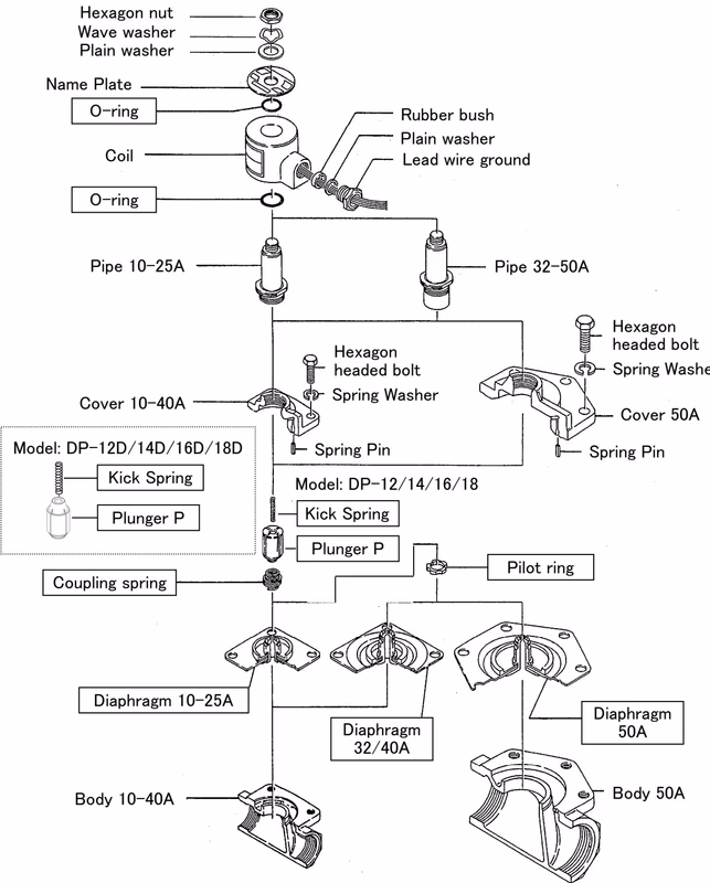
Opening Operation: When the power is turned ON, the coil is magnetized and the plunger is sucked up, thereby opening the pilot valve. The pressure at the upper part of the valve (diaphragm) flows to the outlet side via the pilot port, causing a pressure drop. The diaphragm is then pushed up by the inlet pressure, and the main valve is opened.
Closing Operation: When the power is turned OFF, the plunger is pushed down by a pin/kick spring and dead weight, thereby closing the pilot valve. The inlet pressure is introduced through the bleed port to the upper part of the diaphragm, equalizing the pressure. The diaphragm is then pushed down and closed by the spring.
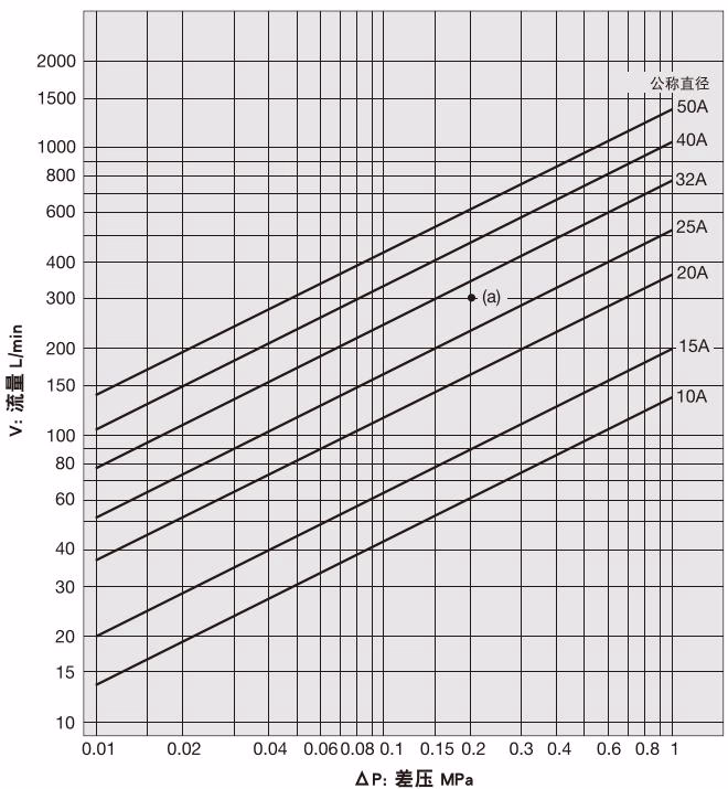
| Nominal size | 15A | 20A | 25A | 32A | 40A | 50A |
|---|---|---|---|---|---|---|
| Cv Value | 4.4 (1.7) | 8.1 (3.2) | 11.5 (4.6) | 17.0 (6.8) | 23.3 (9.3) | 30.5 (12.2) |
Note: In case of inlet/outlet pressure differential being less than 0.01 MPa, the Cv value shown in brackets should be adapted.
Installation Position
When the valve is used at 0.1 MPa or less, mount the valve to horizontal piping with the coil pointing upwards.
Installation and Wiring Warnings
| Problem | Cause | Countermeasure |
|---|---|---|
| Valve does not open | Power is not turned ON. Plunger is stuck by foreign matter. Fluid viscosity is 20cSt or more. | Check and turn on the power. Disassemble and remove foreign matter. Correct viscosity or change model. |
| Valve does not close | Scale or scratch on the plunger or valve disc. Inlet/outlet is in the opposite direction. | Disassemble and clean. Replace if scratched. Reinstall correctly. |
| Abnormal noise | Hexagon nut clamping the coil is loose. Foreign matter exists at the top of plunger. | Tighten it. Disassemble and remove the foreign matter. |
| External leakage | Gasket is damaged or cover tightening is defective. | Replace the gasket. |
Safety Caution
Completely discharge internal pressure from the valves and lines, and cool the valves down to a level where you can touch it with bare hands before disassembly and inspection. Failure to do so may result in injury or burns.
Disassembly Procedure: