


PN25

Yoshitake GD-27GS flanged stainless steel pressure reducing valve for air and non-dangerous fluids. Features 1.0 MPa max inlet pressure and 5-90°C application temperature.
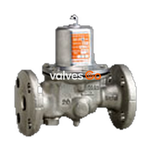
Yoshitake GD-27GS is a direct-acting pressure reducing valve designed for air and other non-dangerous fluids. It features a JIS 10K FF flanged connection and a pressure balance structure that maintains a constant reduced pressure without being affected by inlet pressure fluctuations. The wetted parts are constructed from stainless steel for enhanced corrosion resistance, and it features a low-noise design.
Models in the 20A to 50A nominal size range incorporate a built-in 40 mesh strainer, while sizes 65A to 100A do not include a strainer. A pressure gauge connection port (JIS Rc 1/4 or R1/8) is provided.
| Specification | Value |
|---|---|
| Model | GD-27GS |
| Application | Air, Other non-dangerous fluids |
| Inlet pressure | 1.0 MPa or less |
| Reduced pressure | (A) 0.05 - 0.35 MPa (B) 0.30 - 0.70 MPa |
| Minimum differential pressure | 0.05 MPa |
| Maximum pressure reduction ratio | 10 : 1 |
| Application temperature | 5 - 90 °C |
| Body material | Cast stainless steel |
| Valve seat material | Cast stainless steel / Stainless Steel |
| Valve disc material | EPDM |
| Diaphragm material | EPDM |
| Connection | JIS 10K FF flanged |
WARNING
Please contact the manufacturer when using for gas containing oil. For medium including oil, use fluorine rubber for disc and diaphragm. If not, the disc and diaphragm may be broken.
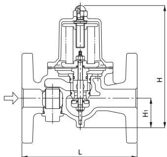
| Nominal size | L (mm) | H (mm) | H1 (mm) | Weight (kg) |
|---|---|---|---|---|
| 20A | 160 | 170 | 41 | 3.9 |
| 25A | 160 | 170 | 41 | 4.8 |
| 32A | 200 | 224 | 57 | 8.0 |
| 40A | 200 | 224 | 57 | 8.3 |
| 50A | 220 | 239.5 | 61 | 10.8 |
| 65A | 220 | 329 | 77 | 20.6 |
| 80A | 230 | 345 | 82 | 22.0 |
| 100A | 270 | 412 | 94 | 34.5 |
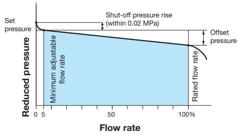
Offset
| Pressure range | Reduced pressure range | Offset |
|---|---|---|
| A | 0.05 - 0.35 MPa | 0.05 MPa or less |
| B | 0.30 - 0.70 MPa | 0.10 MPa or less |
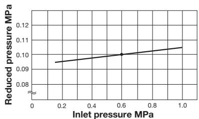
This chart shows variation in reduced pressure when the inlet pressure of 0.6 MPa is changed between 0.15 MPa and 1.0 MPa while the reduced pressure is set at 0.1 MPa.
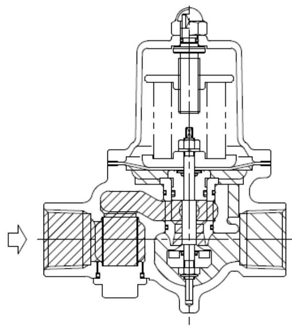
The adjusting screw compresses the adjusting spring, pushes down on the diaphragm, and opens the disc that is directly connected to it. The fluid that entered from the primary side flows out from the upper part of the disk to the secondary side, and at the same time, acts directly on the diaphragm as the secondary side pressure.
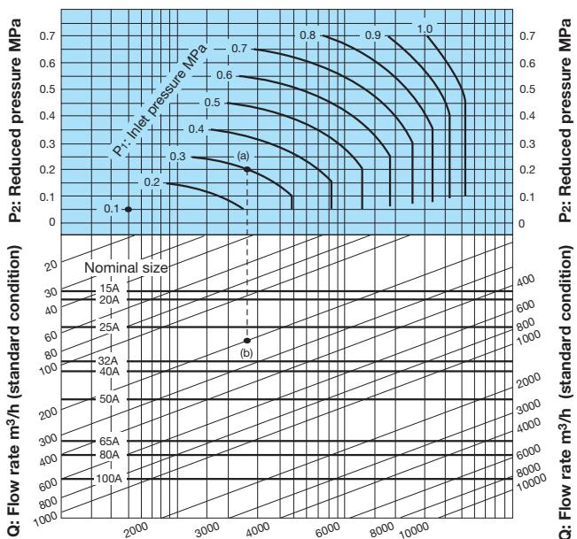
Rated Cv Value
| Nominal size | 15A | 20A | 25A | 32A | 40A | 50A | 65A | 80A | 100A |
|---|---|---|---|---|---|---|---|---|---|
| Rated Cv value | 2 | 2.3 | 3.5 | 6 | 7 | 11 | 21 | 26 | 38 |
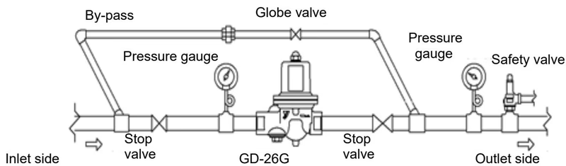
The product can be installed either horizontally or vertically.
Installation Precautions
| Trouble | Cause | Remedy |
|---|---|---|
| Reduced pressure does not reach the desired value. | 1. Working pressure is improper. 2. Nominal size is too small. 3. Pressure adjustment is improper. 4. Built-in strainer is clogged. 5. Pressure gauge is broken. | 1. Correct the working pressure. 2. Replace with proper nominal size. 3. Readjust the pressure. 4. Clean the strainer. 5. Replace pressure gauge. |
| Abnormal pressure rises at the outlet side. | 1. Foreign substances stuck between disc and valve seat, or scratch on them. 2. O-ring is damaged. 3. Diaphragm is damaged. 4. Leakage from the globe valve of bypass line. | 1. Disassemble and remove foreign substances or replace parts. 2. Replace O-ring. 3. Replace diaphragm. 4. Repair or replace globe valve. |
| Abnormal sound | 1. Nominal size is too large for the system. 2. Pressure reduction ratio is too large. 3. Quick operating valve is located near the product. | 1. Replace with proper nominal size. 2. Reduce pressure in two stages. 3. Keep a distance between them as large as possible. |
Clean the strainer regularly at least once or twice a year. Too much deposit of scales decreases the flow rate. Recommended replacement for consumable parts:
Yoshitake Control Valves / Pressure Reducing Valves
GP, GD, and CP series for stable pressure reduction and control in steam, water, and air systems.
Explore similar products in our catalog



