


PN25

Yoshitake GD-45P and GD-45 compact, lightweight direct-acting pressure reducing valves for steam. Features max inlet 2.0 MPa, handle-operated adjustment, and built-in strainer.
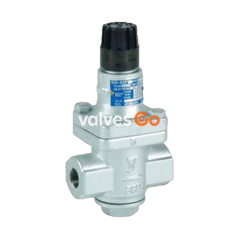
Yoshitake GD-45P and GD-45 are compact and lightweight pressure reducing valves designed for steam applications. They feature a simple structure for easy maintenance and are applicable to inlet pressures up to 2.0 MPa. The GD-45P model includes a handle made of Polyphenylene sulfide (PPS resin) for tool-free pressure adjustment, while both models incorporate an external pressure type bellows for excellent workability and a built-in 60 mesh strainer to protect the valve and seat from dirt.
| Model | GD-45 / GD-45P |
|---|---|
| Application | Steam |
| Inlet pressure | 2.0 MPa or less |
| Reduced pressure | (A) 0.02-0.1 MPa (yellow spring) (B) 0.05-0.4 MPa (blue spring) (C) 0.35-1.0 MPa (yellow green spring) |
| Minimum differential pressure | 0.05 MPa |
| Maximum pressure reduction ratio | 10:1 |
| Maximum temperature | 220°C |
| Valve seat leakage | 0.1% or less of rated flow rate |
| Body Material | Ductile cast iron |
| Valve, valve seat Material | Stainless steel |
| Bellows Material | Phosphor bronze |
| Connection | JIS Rc screwed |
Handle Material
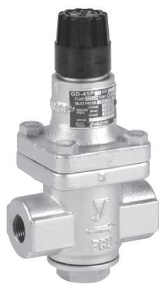
The material of the handle for GD-45P is Polyphenylene sulfide (PPS resin).
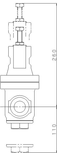
| Nominal size | d | L | H1 | H | Weight (kg) |
|---|---|---|---|---|---|
| 15A | Rc 1/2 | 111 | 47 | 216 | 3.2 |
| 20A | Rc 3/4 | 111 | 47 | 216 | 3.2 |
| 25A | Rc 1 | 111 | 47 | 216 | 3.2 |
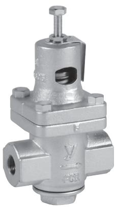
| Nominal size | d | L | H1 | H | Weight (kg) |
|---|---|---|---|---|---|
| 15A | Rc 1/2 | 111 | 47 | 213 | 3.2 |
| 20A | Rc 3/4 | 111 | 47 | 213 | 3.2 |
| 25A | Rc 1 | 111 | 47 | 213 | 3.2 |
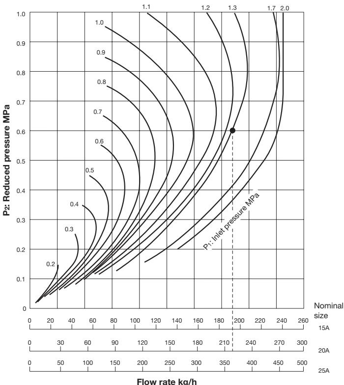
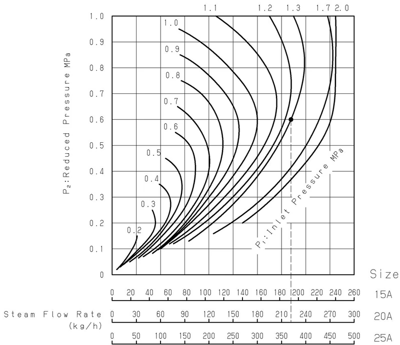
Example: When selecting the nominal size of a pressure reducing valve whose inlet pressure (P1), reduced pressure (P2), and flow rate are 1.3 MPa, 0.6 MPa, and 200 kg/h, respectively, first find the intersection point of the inlet pressure of 1.3 MPa and the reduced pressure of 0.6 MPa. Trace down vertically from this intersection point to find the nominal size with a flow rate of 200 kg/h or over. In this case, the nominal size is 20A. (Set the safety factor at 80 to 90%.)
When the adjusting screw is turned clockwise to compress the spring, the bellows are extended and the spindle opens the valve. When the valve opens, the steam flowing to the outlet side passes through the reduced pressure detection hole, becomes an upwardly directed pressure under the bellows, and balances the force of the spring. The degree of valve opening is adjusted by the balancing of inlet and reduced pressures, thereby stabilizing reduced pressure.
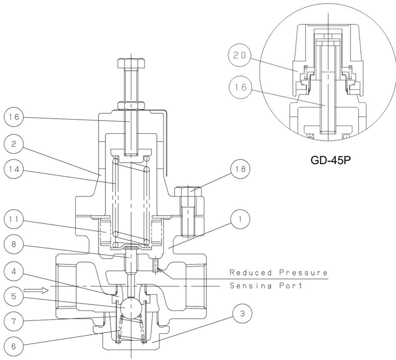
| No. | Parts Name | No. | Parts Name |
|---|---|---|---|
| 1 | Body | 8 | Spindle |
| 2 | Spring Chamber | 11 | Bellows |
| 3 | Cap | 14 | Adjusting Spring |
| 4 | Valve Seat | 16 | Adjusting Screw |
| 5 | Valve | 18 | Bolts |
| 6 | Valve Spring | 20 | Handle (Only GD-45P) |
| 7 | Screen |
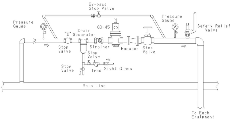
Installation Precautions
Follow the steps below, and slowly turn the adjusting screw/handle to set the pressure. Incorrect adjustment may cause hunting or water hammer.
Adjusting procedure for GD-45P:
Handle Operation (GD-45P)
Press and turn the handle. The handle usually does not rotate due to the stopper. Do not force it to turn or it may get damaged. Do not use tools to turn the handle. The rotation range of the handle is limited.
| Problem | Cause | Solution |
|---|---|---|
| Pressure does not rise to the desired level. | Incorrect pressure is being used. Nominal size is too small. Incorrect adjustment. Strainer or screen is clogged. Pressure gauge malfunction. | Correct the pressure. Replace with correct nominal size. Re-adjust. Disassemble and clean. Replace the pressure gauge. |
| Reduced pressure exceeds prescribed level. | Foreign matter is embedded in the valve/valve seat. Reduced pressure sensing hole is clogged. By-pass valve is leaking. | Disassemble and clean. Polish scratches if they exist. Disassemble and clean. Repair or replace the valve. |
| Abnormal noise is heard. | Pressure reduction ratio is too large. Drainage problem. Abrupt open/close valve is located too close. | Use a two-stage reduction. Install a trap. Increase distance between valves. |
Yoshitake Control Valves / Pressure Reducing Valves
GP, GD, and CP series for stable pressure reduction and control in steam, water, and air systems.
Explore similar products in our catalog



