


PN25

Yoshitake GP-1001 pilot-operated flanged pressure reducing valve for steam with manual handle. Features ductile cast iron body, 0.1-1.0 MPa inlet pressure, and 20:1 max reduction ratio.
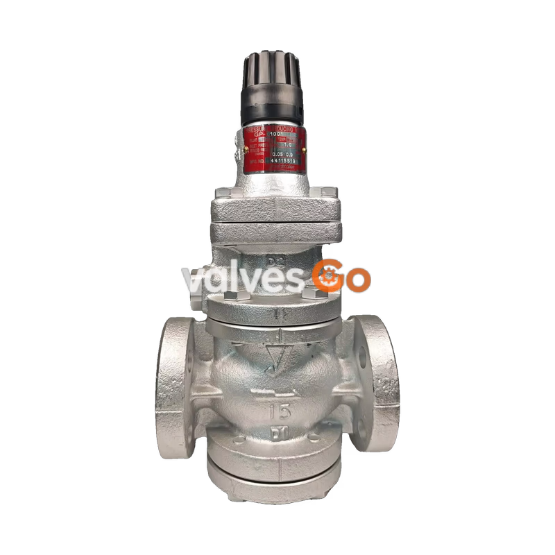
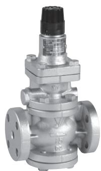
Yoshitake GP-1001 is a pilot-operated pressure reducing valve designed for steam applications, uniquely equipped with a manual handle for straightforward pressure adjustment. It features a ductile cast iron body and a spherical main valve that offers excellent sealability, greatly reducing valve seat leakage (compliant with ANSI Class IV). This model is highly suitable for building utilities, air-conditioning systems, and factory systems where precise steam pressure control and frequent manual adjustments are required.
| Specification | Value |
|---|---|
| Application | Steam |
| Inlet Pressure | 0.1–1.0 MPa |
| Reduced Pressure | 0.05–0.9 MPa (90% or less of inlet pressure) |
| Minimum Differential Pressure | 0.05 MPa |
| Maximum Pressure Reduction Ratio | 20:1 |
| Maximum Temperature | 220°C |
| Valve Seat Leakage | 0.01% or less of rated flow |
| Body Material | Ductile cast iron |
| Valve / Valve Seat Material | Stainless steel |
| Piston / Cylinder Material | Brass or bronze |
| Connection | JIS 10K FF flanged |
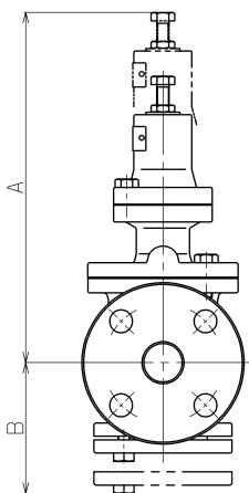
| Nominal Size | L (mm) | H1 (mm) | H (mm) | Weight (kg) |
|---|---|---|---|---|
| 15A | 150 | 64 | 285 | 8.0 |
| 20A | 155 | 64 | 285 | 8.5 |
| 25A | 160 | 67 | 300 | 10.0 |
| 32A | 190 | 82 | 323 | 14.0 |
| 40A | 190 | 82 | 323 | 14.5 |
| 50A | 220 | 93 | 347 | 20.0 |
| 65A | 245 | 100 | 357 | 30.0 |
| 80A | 290 | 122 | 404 | 35.0 |
| 100A | 330 | 144 | 450 | 52.5 |
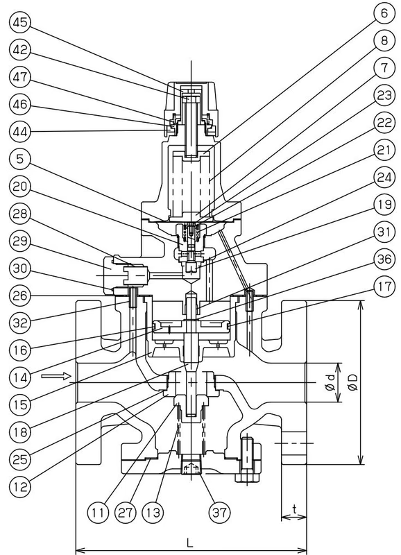
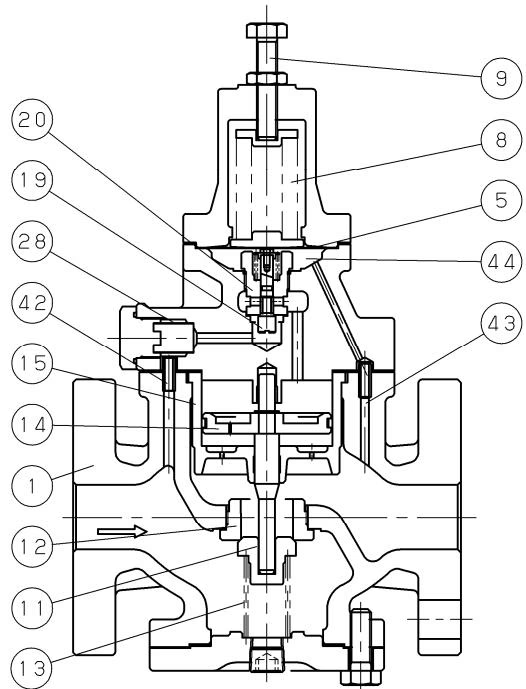
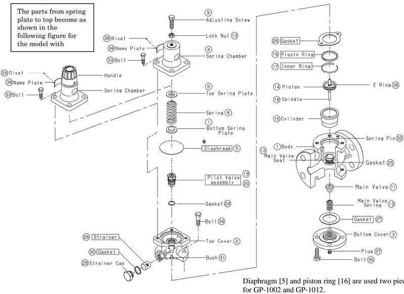
The pressure-reducing valve reduces pressure by throttling the valve. It is composed of a main valve and main valve seat for throttling, along with an adjusting spring, diaphragm, pilot valve, and piston for pressure sensing and activation.
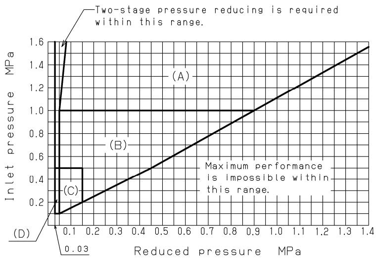
Find the intersection point of the inlet and reduced pressures. The valve is suitable if the point falls within the indicated range.
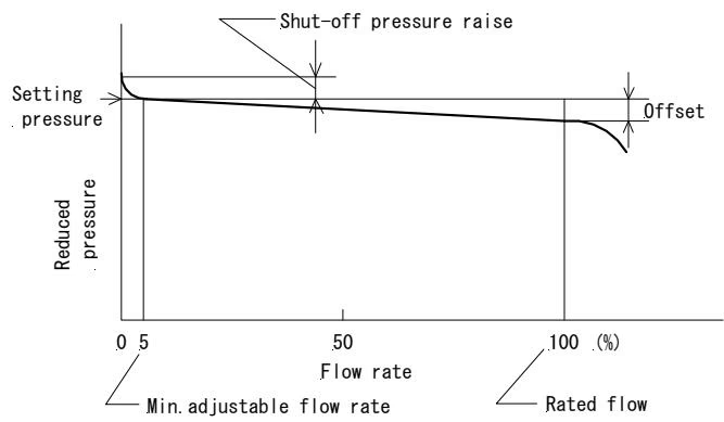
Flow Rate Characteristics
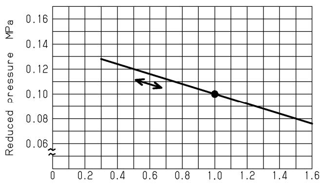
Pressure Characteristics The chart indicates variation in reduced pressure when the inlet pressure changes from 1.6 to 0.3 MPa, with reduced pressure set to 0.1 MPa at an inlet of 1.0 MPa.
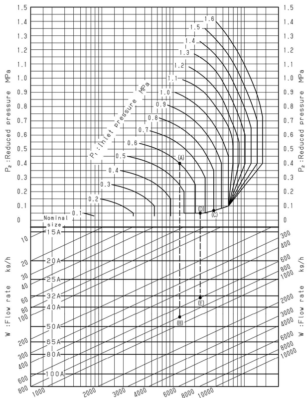
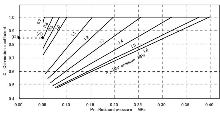
If the inlet pressure exceeds 0.7 MPa and the reduced pressure is 0.4 MPa or less, find the appropriate correction coefficient C using the chart below, and multiply the rated Cv value to obtain the corrected Cv value.
Installation Precautions
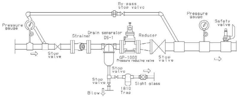
Provide space on the top and bottom of the valve so that it can be easily disassembled and inspected.
Operation Notes
Close the stop valves before and after the valve, and remove all foreign matter and scales via the by-pass line before operation. For the model with a handle, be sure to operate the handle manually and turn it while pushing down. Do not turn with too much torque or excessively.
| Problem | Possible Cause | Countermeasure |
|---|---|---|
| Desired pressure cannot be reached | 1. Inappropriate operating pressure. 2. Strainer clogged. 3. Foreign matter on piston/cylinder. 4. Damaged piston ring. 5. Nominal size too small. | 1. Adjust to proper value. 2. Disassemble and clean. 3. Remove foreign matter or replace parts. 4. Replace piston ring. 5. Change to suitable nominal size. |
| Secondary pressure rises above set value | 1. Foreign matter on main valve/seat. 2. Foreign matter on pilot valve/seat. 3. Piston/cylinder obstructed. 4. No steam trap at line end. 5. By-pass valve leaking. 6. Diaphragm damaged. | 1. Clean or replace parts. 2. Clean or replace pilot valve unit. 3. Remove foreign matter. 4. Install a steam trap. 5. Repair or replace. 6. Replace diaphragm. |
| External leakage | Gasket damaged/deteriorated or diaphragm broken. | Replace gasket or diaphragm. |
| Abnormal noise | 1. Flow rate too low. 2. High pressure reduction ratio. 3. Condensate problem. | 1. Choose a proper nominal size. 2. Use two-stage reduction. 3. Install a steam trap. |
Yoshitake Control Valves / Pressure Reducing Valves
GP, GD, and CP series for stable pressure reduction and control in steam, water, and air systems.
Explore similar products in our catalog



