


PN25

Yoshitake GP-1010TS pilot-operated pressure reducing valve for air and non-corrosive gases. Features JIS Rc screwed connection, stainless steel trim parts, and 0.05-0.9 MPa reduced pressure.
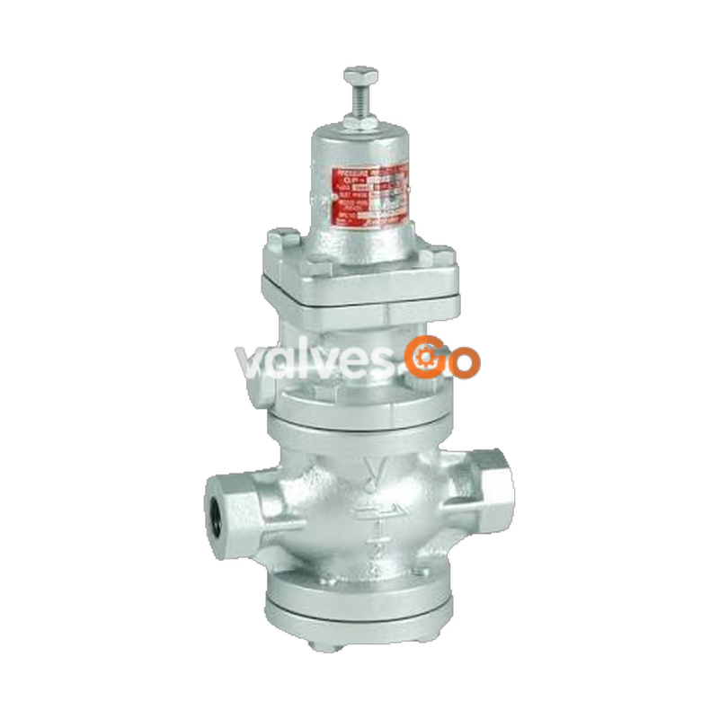
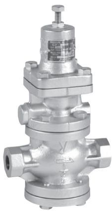
Yoshitake GP-1010TS is a pilot-operated pressure reducing valve designed for air and non-corrosive gases. As a specialized variant within the GP-1000T series, the GP-1010TS features stainless steel trim parts (piston, cylinder, and valve) and a JIS Rc screwed connection. It provides reliable control for small to large flow rates in building utility systems, air-conditioning systems, and factory applications.
The valve offers significantly improved workability and durability over conventional pressure reducing valves. It achieves zero valve seat leakage due to the refined design of its sliding parts and features a simple, robust internal structure.
| Specification | Value |
|---|---|
| Application | Air, Other non-dangerous fluids / non-corrosive gases |
| Inlet Pressure | 0.1 - 1.0 MPa |
| Reduced Pressure | 0.05 - 0.9 MPa (90% or less of inlet pressure) |
| Minimum Differential Pressure | 0.05 MPa |
| Maximum Pressure Reduction Ratio | 20:1 |
| Application Temperature | 5 - 80°C |
| Valve Seat Leakage | None |
| Connection | JIS Rc screwed |
| Part | Material |
|---|---|
| Body | Ductile cast iron |
| Valve | Stainless steel (NBR incorporated) |
| Valve Seat | Stainless steel |
| Piston, Cylinder | Stainless steel |
| Diaphragm | Stainless steel |
Stainless Steel Trim
The GP-1010TS model is explicitly built with stainless steel trim components (piston, cylinder, and valve) for improved corrosion resistance and durability compared to the standard GP-1010T.
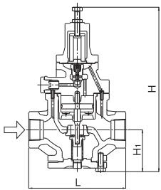
| Nominal Size | d | L (mm) | H1 (mm) | H (mm) | Weight (kg) |
|---|---|---|---|---|---|
| 15A | Rc 1/2 | 150 | 64 | 285 | 7.0 |
| 20A | Rc 3/4 | 155 | 64 | 285 | 7.0 |
| 25A | Rc 1 | 160 | 67 | 300 | 8.5 |
| 32A | Rc 1-1/4 | 190 | 82 | 323 | 12.0 |
| 40A | Rc 1-1/2 | 190 | 82 | 323 | 12.5 |
| 50A | Rc 2 | 220 | 93 | 347 | 18.0 |
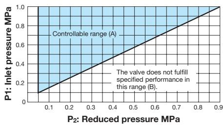
Find the intersection point of the inlet and reduced pressures. The valve is suitable within range (A). If the intersection point lies in range (B), maximum performance cannot be obtained.
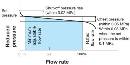
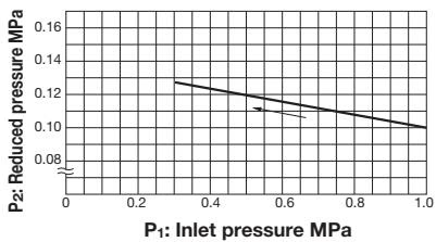
This chart shows the variation in reduced pressure when the inlet pressure of 1.0 MPa is changed between 0.3 MPa and 1.0 MPa while the reduced pressure is set at 0.1 MPa.
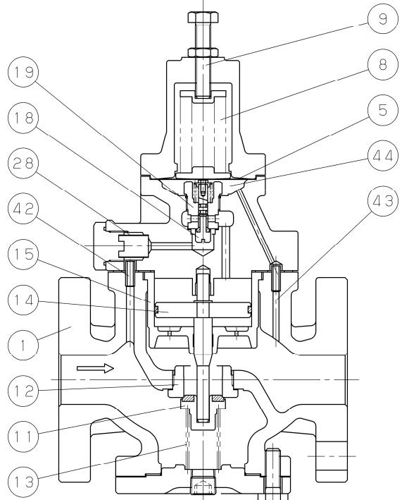
The valve reduces pressure by throttling. It is composed of a main valve and main valve seat for throttling, and an adjusting spring, diaphragm, pilot valve, and piston for pressure sensing and activation.
Installation Precautions
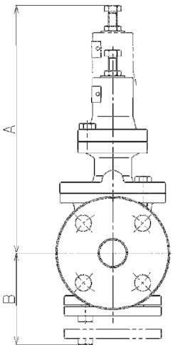
Provide adequate space on the top and bottom of the valve so it can be easily disassembled and inspected. For nominal sizes 15A to 25A, provide 310 mm (A) and 135 mm (B) clearance for the spring type.
Maintenance Note
Foreign matter and scales in a pipe cause most pressure reducing valve problems. Completely discharge internal pressure and cool the valve before disassembly.
Yoshitake Control Valves / Pressure Reducing Valves
GP, GD, and CP series for stable pressure reduction and control in steam, water, and air systems.
Explore similar products in our catalog



