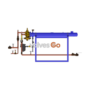
Feed-Forward Design

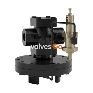
Yoshitake GPR-2000 primary pressure regulating valve for steam. External sensing type with 0.02-1.4 MPa pressure regulation range and stainless steel parts.
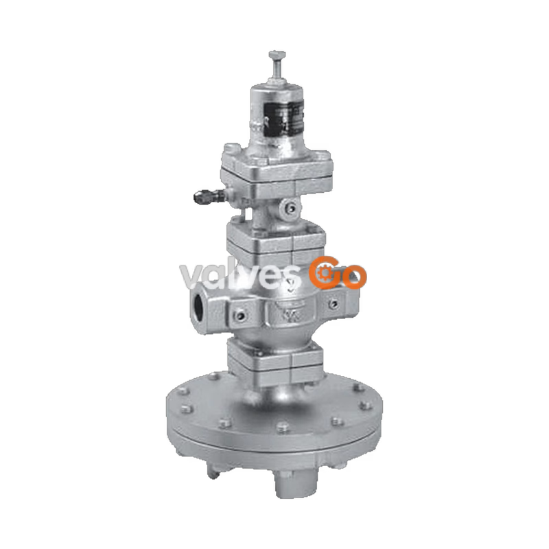
Yoshitake GPR-2000 primary pressure regulating valves for steam are diaphragm-type, pilot-operated primary pressure regulating valves applicable for heavy-duty use over a wide range of flow rates. Typical applications include construction sites, air-conditioning plants, and factory facilities.
Key features include large capacity with distinguished performance, and excellent sealability ensured by a spherical valve. The main valve, main valve seat, pilot valve, and pilot valve seat are made of stainless steel for distinguished durability. The valve offers a wide pressure adjustment range of 0.02 to 1.4 MPa depending on the specific model specifications.
 Screwed type
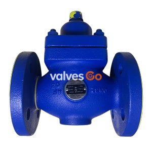
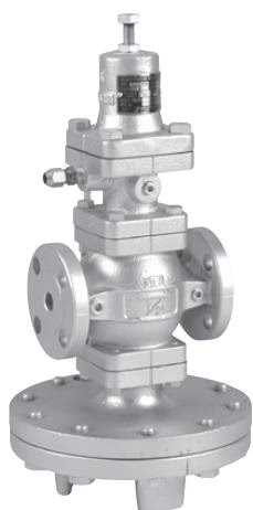 Flanged type
| Application | Steam |
| Primary pressure sensing method | External sensing type *1 |
| Pressure regulating range | 0.02-0.15 MPa *2 0.1-1.0 MPa 1.0-1.4 MPa |
| Minimum differential pressure | 15% of set pressure (gauge pressure) (Minimum value: 0.10 MPa) |
| Fluid temperature | 220℃ or less |
| Valve seat leakage | 0.01% of rated flow rate |
| Body Material | Ductile cast iron (FCD450) |
| Main valve Material | Stainless steel |
| Valve seat Material | Stainless steel |
| Pilot valve Material | Stainless steel |
| Pilot valve seat Material | Stainless steel |
| Diaphragm Material | Stainless steel |
| Connection | JIS Rc screwed, JIS 20K RF flanged, JIS 10K FF flanged |
INFO
*1 External sensing method is used for the product because of controllability(performance). Available with internal sensing type, but the Cv value is different. *2 When the set pressure is between 0.02 MPa and 0.1 MPa, back pressure should not exist.
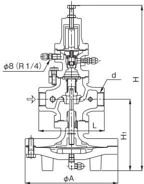
| Nominal size | d | L (mm) | H1 (mm) | H (mm) | A (mm) | Weight (kg) |
|---|---|---|---|---|---|---|
| 15A | Rc 1/2 | 150 | 170 | 398 | 200 | 14.5 |
| 20A | Rc 3/4 | 150 | 170 | 398 | 200 | 14.5 |
| 25A | Rc 1 | 160 | 175 | 404 | 226 | 18.8 |
| 32A | Rc 1-1/4 | 180 | 192 | 434 | 226 | 22.0 |
| 40A | Rc 1-1/2 | 180 | 192 | 434 | 226 | 22.0 |
| 50A | Rc 2 | 230 | 216 | 498 | 276 | 33.6 |
Available with NPT connection.
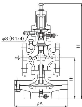
| Nominal size | L (mm) | H1 (mm) | H (mm) | A (mm) | Weight (kg) |
|---|---|---|---|---|---|
| 15A | 146 (142) | 170 | 398 | 200 | 16.0 (15.8) |
| 20A | 146 (142) | 170 | 398 | 200 | 16.5 (16.3) |
| 25A | 156 (152) | 175 | 404 | 226 | 21.5 (21.1) |
| 32A | 176 (172) | 192 | 434 | 226 | 24.5 (24.0) |
| 40A | 196 (192) | 192 | 434 | 226 | 25.0 (24.6) |
| 50A | 222 (218) | 216 | 498 | 276 | 36.6 (36.4) |
| 65A | 282 (278) | 251 | 552 | 352 | 64.9 (64.6) |
| 80A | 302 (294) | 264 | 575 | 352 | 72.1 (69.9) |
| 100A | 342 (330) | 321 | 658 | 401 | 108.0 (104.0) |
INFO
Specifications Chart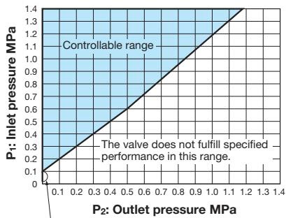 In this range, keep the outlet pressure at 0 MPa.
Flow Rate Characteristics Chart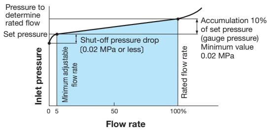
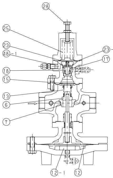
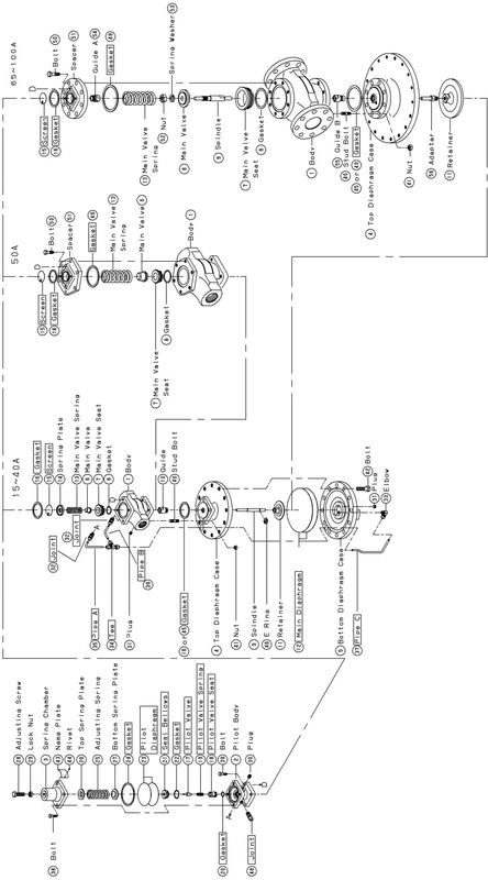
| No. | Parts name |
|---|---|
| 1 | Body |
| 2 | Pilot body |
| 6 | Main valve |
| 7 | Main valve seat |
| 12 | Main diaphragm |
| 13 | Main valve spring |
| 15 | Screen |
| 17 | Pilot valve |
| 18 | Pilot valve seat |
| 23 | Pilot diaphragm |
| 25 | Spring |
| 28 | Adjusting Screw |
| 32 | Joint |
| 33 | Elbow |
| 35,36,37 | Pipe A, B, C |
| 12-1 | Main diaphragm chamber |
| 23-1 | Pilot diaphragm chamber |
| 48-1 | Inlet pressure sensing port |
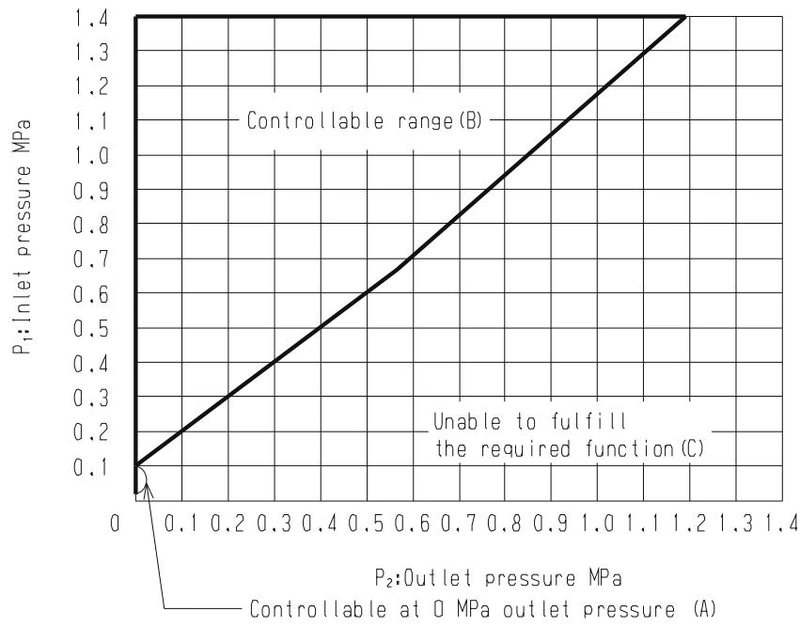
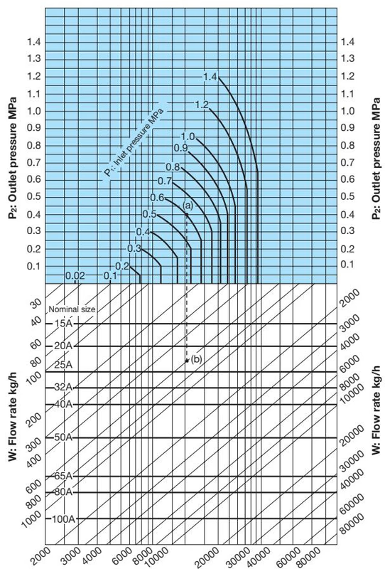
Find the point of intersection of primary and secondary pressure, in case that the point is located within the range A and B, the valve is suitable to regulate the pressure.
For example, take a primary pressure regulating valve whose inlet pressure(P1) is 0.6 MPa, outlet pressure(P2) 0.4 MPa, flow rate 600 kg/h. When determining the nominal size, find the point of intersection(A) of inlet pressure 0.6 MPa and outlet pressure 0.4 MPa. Vertically proceed from point(A) to come across the flow rate 600 kg/h, and regard this point as (B). Point(B) is between nominal sizes 20A and 25A. Select the larger nominal size (in this example, nominal size 25A).
In case selecting the suitable valve size from calculation, find the Cv value with formula, which value will be defined by applying criteria, and select the valve size that fulfills the said Cv value.
Cv value chart
| 15A | 20A | 25A | 32A | 40A | 50A | 65A | 80A | 100A |
|---|---|---|---|---|---|---|---|---|
| 5.0 | 7.2 | 10.9 | 14.3 | 18.8 | 32.0 | 60.0 | 78.0 | 120.0 |
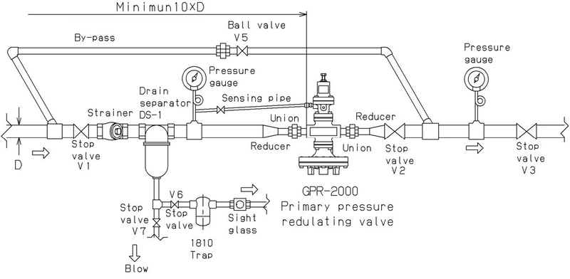
Warning
(1) As this product is considerably heavy in weight, please secure it with lifting devices for installation on piping.
(2) When installing the combination valve, be sure to connect the provided sensing pipe and joint.
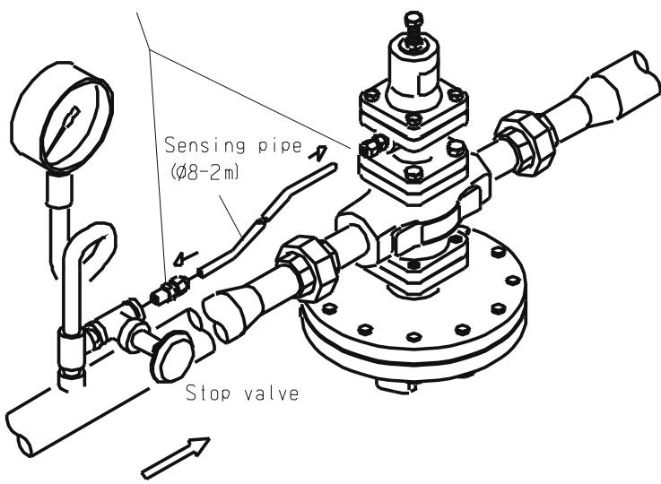 Fig.1 Connect the provided sensing pipe (φ8-2m) and joint (φ8-R1/4) as shown in the illustration in Fig.1.
Caution
(1) Do not disassemble the valve unreasonably. (2) Remove foreign matter and scales from the lines before connecting the valve. (3) Install a strainer (80 mesh) at the valve inlet side. (4) Install a pressure gauge at both the inlet and outlet sides of the valve. Further, install the gauge at the outlet side as close to the sensing pipe (pressure sensing side) as possible. (5) Install a trap to the bottom of rising pipes and the end of other pipes connected to the inlet and outlet sides of the valve. When connecting a branch pipe from the main line, be sure to connect the trap draining drip leg from the bottom of the main line. (6) Install the valve perpendicularly to horizontal lines with the diaphragm chamber located at the bottom. (7) Be extremely careful not to damage the copper pipe. (8) Do not apply excessive load, torque or vibration to the valve. (9) Use the sensing pipe (φ8-2m) and joint (φ8-R1/4) provided. (10) Use the gate valve as a stop valve at the inlet and outlet sides of the combination valve. (11) When installing, reserve the space shown below (Fig.2) in both upper and lower side of the pipe center of the product for the maintenance and checking.
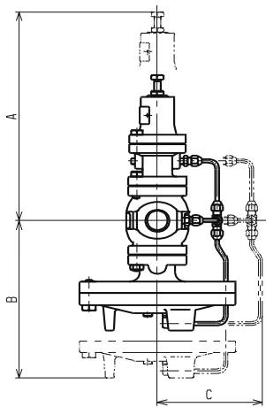 Fig.2
Fig.2
| Size | A (mm) | B (mm) | C (mm) |
|---|---|---|---|
| 15A, 20A | 340 | 340 | 180 |
| 25A | 340 | 350 | 200 |
| 32A, 40A | 360 | 380 | 200 |
| 50A | 400 | 430 | 220 |
| 65A | 420 | 370 | 260 |
| 80A | 430 | 390 | 260 |
| 100A | 450 | 470 | 280 |
Yoshitake Control Valves / Self-operated Regulators
OB, GPR, CF, and GD series self-operated regulators for pressure and temperature control without external power.
Explore similar products in our catalog