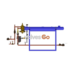
Feed-Forward Design

The Yoshitake OB-30 and OB-31 series are direct-acting bellows temperature regulators for heating and cooling. Features a bronze body, PTFE valve disc, and handles up to 1.0 MPa and 185°C.
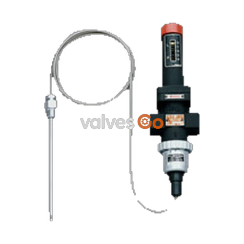
The Yoshitake OB-30 and OB-31 series are direct-acting bellows temperature regulators designed for precise temperature control in heating and cooling applications. Featuring a bronze body and a soft PTFE valve seat, these regulators offer excellent durability and high sealability. The single valve and balance bellows structure ensures stable temperature control without being affected by inlet pressure fluctuations.
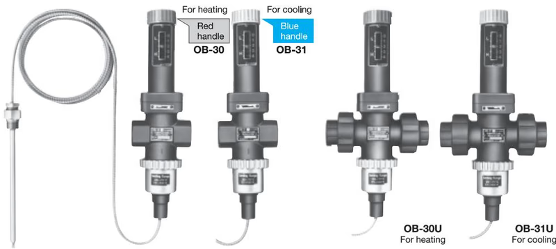
| Model | OB-30 | OB-30U | OB-31 | OB-31U |
|---|---|---|---|---|
| Purpose | For heating | For heating | For cooling | For cooling |
| Application | Steam, Hot water | Steam, Hot water | Cold water, Refrigerant | Cold water, Refrigerant |
| Maximum pressure | 1.0 MPa (1.7 MPa for hot water) | 1.0 MPa (1.7 MPa for hot water) | 1.7 MPa | 1.7 MPa |
| Max. differential pressure | 1.0 MPa | 1.0 MPa | 1.0 MPa | 1.0 MPa |
| Valve seat leakage | 0.05% or less of rated flow rate | 0.05% or less of rated flow rate | 0.05% or less of rated flow rate | 0.05% or less of rated flow rate |
| Max. temperature | 185°C | 185°C | 185°C | 185°C |
| Material (Body) | Bronze | Bronze | Bronze | Bronze |
| Material (Valve) | Brass (PTFE) | Brass (PTFE) | Brass (PTFE) | Brass (PTFE) |
| Material (Valve seat) | Stainless steel | Stainless steel | Stainless steel | Stainless steel |
| Connection | JIS Rc screwed | JIS Rc screwed (union joint) | JIS Rc screwed | JIS Rc screwed (union joint) |
| Specification | Details |
|---|---|
| Heated/Cooled fluid | Cold and hot water, Oil, Liquid |
| Maximum pressure | 1.0 MPa |
| Material (Thermal bulb) | Copper pipe (nickel chrome plated) * |
| Material (Capillary) | Copper pipe |
| Material (Capillary tube) | Stainless steel |
| Standard capillary length | 2 m |
| Connection | JIS R 1/2 |
| Temperature adjusting range (°C) | Withstand temperature (°C) |
|---|---|
| 0-35 | 75 |
| 25-70 | 110 |
| 40-100 | 140 |
| 60-130 | 170 |
| 70-150 | 190 |
INFO
| Nominal size | d | L (OB-30/31) | Weight (OB-30/31) | L (OB-30U/31U) | Weight (OB-30U/31U) |
|---|---|---|---|---|---|
| 15A | Rc 1/2 | 75 mm | 2.1 kg | 160 mm | 3.1 kg |
| 20A | Rc 3/4 | 80 mm | 2.2 kg | 160 mm | 3.1 kg |
| 25A | Rc 1 | 90 mm | 2.4 kg | 160 mm | 3.1 kg |
| Capillary length | Weight |
|---|---|
| 2 m | 0.6 kg |
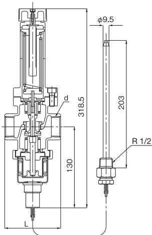 OB-30
OB-30
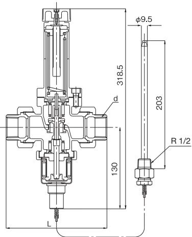 OB-31U
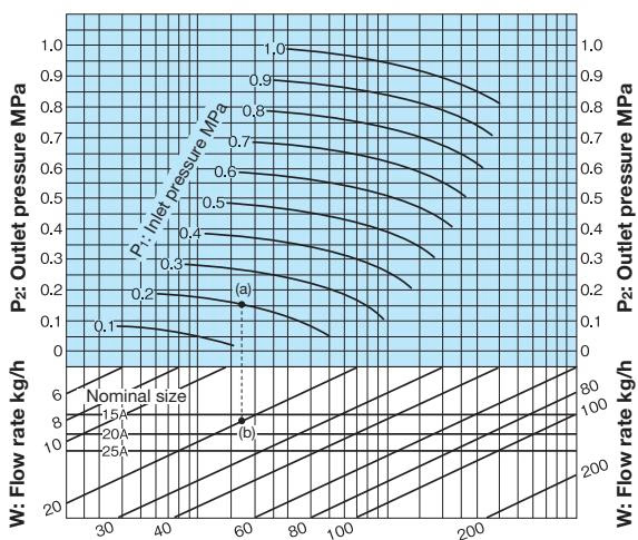
How to use the chart: When selecting the nominal size of a temperature regulator whose inlet pressure (P1), outlet pressure (P2), and steam flow rate are 0.2 MPa, 0.15 MPa, and 20 kg/h, respectively, first find intersection point (a) of the inlet pressure of 0.2 MPa and the outlet pressure of 0.15 MPa. Trace down vertically from this intersection point (a) to find intersection point (b) with the flow rate of 20 kg/h. Since this intersection point (b) lies between nominal sizes 15A and 20A, select the larger one, 20A.
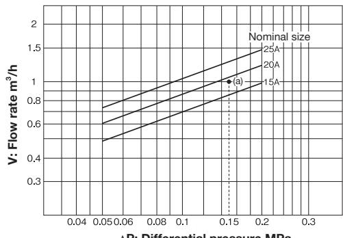
How to use the chart: When selecting the nominal size of a temperature regulator whose inlet pressure, outlet pressure, and flow rate are 0.3 MPa, 0.15 MPa, and 1 m³/h, respectively, first find intersection point (a) of the differential pressure (ΔP) of 0.15 MPa (0.3 MPa – 0.15 MPa) before and after the valve and the flow rate of 1 m³/h. Since this intersection point (a) lies between nominal sizes 15A and 20A, select the larger one, 20A.
INFO
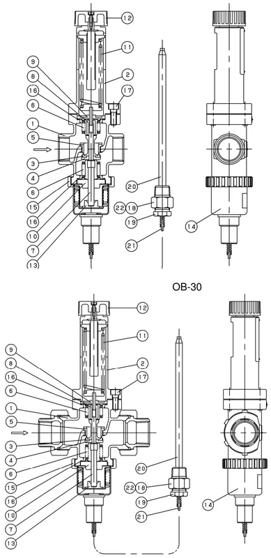 OB-30U
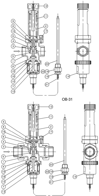 OB-31U
| No. | Part name | No. | Part name |
|---|---|---|---|
| 1 | Body | 12 | Handle |
| 2 | Spring chamber | 13 | Bellows follower |
| 3 | Disc | 14 | Bellows |
| 4 | Valve | 15 | Ring |
| 5 | Valve seat | 16 | Gasket |
| 6 | Balance bellows | 17 | Bolt |
| 7 | Spindle | 18 | Bushing |
| 8 | Nut | 19 | Washer of packing |
| 9 | Guide | 20 | Thermal bulb |
| 10 | Guide | 21 | Capillary tube |
| 11 | Spring | *22 | Packing |
The parts marked "" are available as consumable supply.*
Heating the thermal bulb [20] makes its inner pressure rise, while cooling it makes the pressure lower. The bellows [14] expands/contracts responding to the change in the internal pressure that is transmitted through the capillary tube [21], and this allows the valve [4] open/close.
Precaution for installation
TIP
The thermal bulb is made of copper and can be easily bent if it bumps against something. Handle with care.
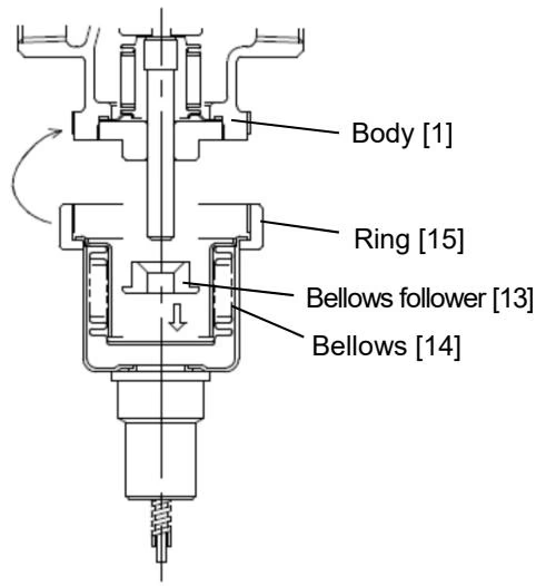
Place the bellows follower [13], which is packaged with the body, into the bellows [14] with its flat surface facing downward and then screw it into the lower surface of the body [1] by the ring [15].
It makes the assembly easier to loosen the handle [12] to direction of the "L" position. Be sure not to lose the bellows follower because the product does not function properly without it.
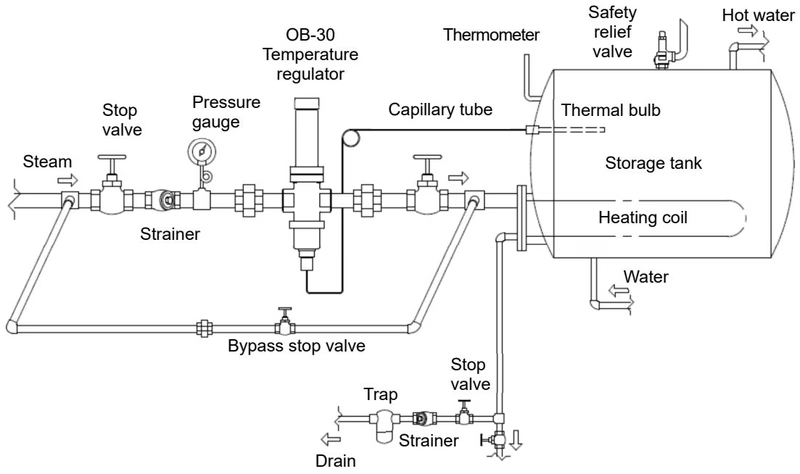 OB-30, OB-30U (for heating)
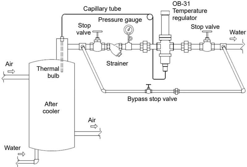 OB-31, OB-31U (for cooling)
Precaution for operation
Taking a wrong adjusting procedure may cause hunting, scale problems or water hammer, and can heavily damage the main parts of the product. Be sure to follow the procedure below.
Scale reading and set temperature
| Scale reading | OB-30, OB-30U (for heating) | ||||
|---|---|---|---|---|---|
| 0-35°C | 25-70°C | 40-100°C | 60-130°C | 70-150°C | |
| 0 | -10°C | 14°C | 28°C | - | - |
| 1 | 5°C | 30°C | 47°C | 58°C | 67°C |
| 2 | 20°C | 46°C | 66°C | 81°C | 91°C |
| 3 | 31°C | 62°C | 86°C | 105°C | 119°C |
| 4 | 42°C | 78°C | 106°C | 132°C | 162°C |
| Scale reading | OB-31, OB-31U (for cooling) | ||
|---|---|---|---|
| 0-35°C | 25-70°C | 40-100°C | |
| 0 | - | - | - |
| 1 | -14°C | 11°C | 23°C |
| 2 | 9°C | 38°C | 55°C |
| 3 | 32°C | 65°C | 94°C |
| 4 | 55°C | 98°C | 141°C |
The tables above show the set temperature per scale reading as a guide. Because the temperature varies slightly according to the conditions of use, adjust the handle till the desired temperature is obtained.
Precaution for inspection
Inspection must be done by experienced professional or valve manufacturer. Completely discharge the pressure inside of the product, piping and equipment prior to disassembly and inspection. When fluid is hot, cool down the product to the condition that it can be touched with bare hands. Failure to follow this notice may result in scalds, injury or contamination on the surroundings due to the residual pressure.
WARNING
OB-30, OB-30U
| Trouble | Cause | Remedy |
|---|---|---|
| Temperature does not rise. | 1. Inadequate adjustment. 2. Insufficient drainage from the trap of heat exchanger, etc. | 1. Readjust according to Adjustment procedure. 2. Check the trap and replace it if necessary. |
| Temperature rises excessively. | 1. Inadequate adjustment. 2. Foreign substances stuck or damage on the disc [3] and valve seat [5]. 3. The thermal bulb [20] or bellows [14] is damaged. | 1. Readjust according to Adjustment procedure. 2. Remove the foreign substances. If there is damage, replace the parts. 3. Replace the sensor. |
| Large error of temperature control. | 1. The thermal bulb [20] and thermometer are installed in wrong positions. 2. Inlet pressure is too high. | 1. Reinstall them at points where the circulation is best. 2. When steam consumption is small, lower the inlet pressure for better temperature control. |
| Outside leakage. | 1. Leakage from the gasket [16]. 2. Balance bellows [6] is damaged. | 1. Retighten the gasket, or replace the part. 2. Disassemble the product and replace the part. |
OB-31, OB-31U
| Trouble | Cause | Remedy |
|---|---|---|
| Temperature does not lower. | 1. Inadequate adjustment. 2. The thermal bulb [20] or bellows [14] is damaged. | 1. Readjust according to Adjustment procedure. 2. Replace the sensor. |
| Temperature lowers excessively. | 1. Inadequate adjustment. 2. Foreign substances stuck or damage on the disc [3] and valve seat [5]. | 1. Readjust according to Adjustment procedure. 2. Remove the foreign substances. If there is damage, replace the parts. |
| Large error of temperature control. | 1. The thermal bulb [20] and thermometer are installed in wrong positions. 2. Inlet pressure is too high. | 1. Reinstall them at points where the circulation is best. 2. When steam consumption is small, lower the inlet pressure for better temperature control. |
| Outside leakage. | 1. Leakage from the gasket [16]. 2. Balance bellows [6] is damaged. | 1. Retighten the gasket, or replace the part. 2. Disassemble the product and replace the part. |
Yoshitake Control Valves / Self-operated Regulators
OB, GPR, CF, and GD series self-operated regulators for pressure and temperature control without external power.
Explore similar products in our catalog