Feed-Forward Design

Yoshitake OB-31 direct-acting bellows soft seat temperature regulator for cooling applications. Features 1.7 MPa max pressure and stable control.
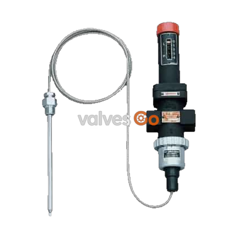
Yoshitake OB-31 and OB-31U are direct-acting type bellows soft seat temperature regulators designed for cooling applications using cold water or refrigerant. The OB-31 features a JIS Rc screwed connection, while the OB-31U uses a union joint. The series also includes the OB-30 and OB-30U, which are designed for heating applications using steam or hot water. These regulators feature a single valve and balance bellows structure that offers stable temperature control without being affected by inlet pressure fluctuations. The valve parts are constructed of stainless steel and fluororesin, ensuring excellent durability and high sealability.
| Model | OB-31 / OB-31U | OB-30 / OB-30U |
|---|---|---|
| Purpose | For cooling | For heating |
| Application | Cold water, Refrigerant | Steam, Hot water |
| Maximum Pressure | 1.7 MPa | 1.0 MPa (1.7 MPa for hot water) |
| Max. Differential Pressure | 1.0 MPa | 1.0 MPa |
| Valve Seat Leakage | 0.05% or less of rated flow rate | 0.05% or less of rated flow rate |
| Max. Temperature | 185 °C | 185 °C |
| Material (Body) | Bronze | Bronze |
| Material (Valve) | Brass (PTFE) | Brass (PTFE) |
| Material (Valve Seat) | Stainless steel | Stainless steel |
| Connection | JIS Rc screwed (OB-31) / JIS Rc screwed with union joint (OB-31U) | JIS Rc screwed (OB-30) / JIS Rc screwed with union joint (OB-30U) |
| Heated Fluid | Cold and hot water, Oil, Liquid | | Cooled Fluid | Cold and hot water, Oil, Liquid | | Maximum Pressure | 1.0 MPa | | Material (Thermal Bulb) | Copper pipe (Nickel chrome plated) * | | Material (Capillary Tube) | Copper pipe | | Material (Flexible Tube) | Stainless steel | | Standard Capillary Length | 2 m (Optional 3 m or 5 m available) | | Connection | JIS R 1/2 screwed |
*Available with a thermal well (stainless steel).
| Temperature Adjusting Range (°C) | Withstand Temperature (°C) |
|---|---|
| 0–35 | 75 |
| 25–70 | 110 |
| 40–100 | 140 |
| 60–130 | 170 |
| 70–150 | 190 |
Note: The maximum temperature of the thermal bulb for cooling is 100°C.The term "withstand temperature" means the temperature from pressure resistance of the bellows.
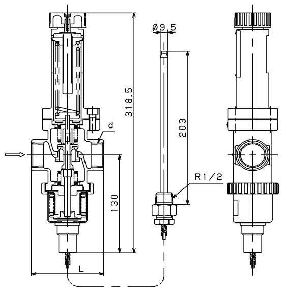
| Nominal Size | d | L (mm) | Weight (kg) |
|---|---|---|---|
| 15A | Rc 1/2 | 75 | 2.1 |
| 20A | Rc 3/4 | 80 | 2.2 |
| 25A | Rc 1 | 90 | 2.4 |
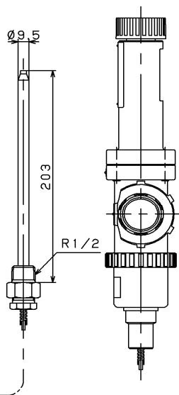
| Nominal Size | d | L (mm) | Weight (kg) |
|---|---|---|---|
| 15A | Rc 1/2 | 160 | 3.1 |
| 20A | Rc 3/4 | 160 | 3.1 |
| 25A | Rc 1 | 160 | 3.1 |
| Capillary Length | Weight |
|---|---|
| 2 m | 0.6 kg |
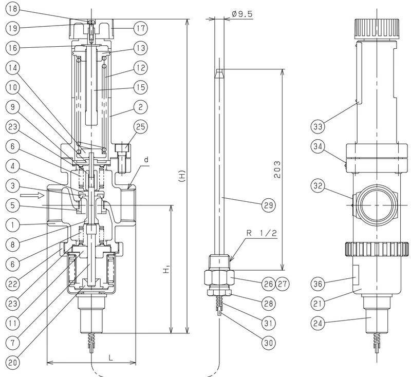
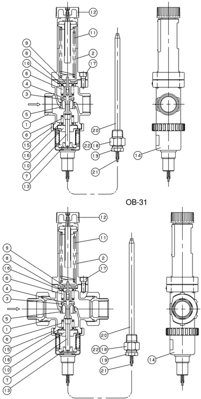
| No. | Part Name | No. | Part Name |
|---|---|---|---|
| 1 | Body | 12 | Handle |
| 2 | Spring chamber | 13 | Bellows follower |
| 3 | Disc | 14 | Bellows |
| 4 | Valve | 15 | Ring |
| 5 | Valve seat | 16 | Gasket |
| 6 | Balance bellows | 17 | Bolt |
| 7 | Spindle | 18 | Bushing |
| 8 | Nut | 19 | Washer of packing |
| 9 | Guide | 20 | Thermal bulb |
| 10 | Guide | 21 | Capillary tube |
| 11 | Spring | 22 | Packing |
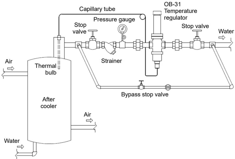
Heating the thermal bulb makes its inner pressure rise, while cooling it makes the pressure lower. The bellows expands or contracts responding to the change in the internal pressure that is transmitted through the capillary tube, and this allows the valve to open or close. For the OB-31 and OB-31U (cooling), when the temperature of the thermal bulb rises, the bellows expands and applies lifting force to the spindle to open the valve. When the temperature lowers, the downward force applied to the spindle by the spring closes the valve. The set temperature can be adjusted by turning the handle to change the load of the spring.
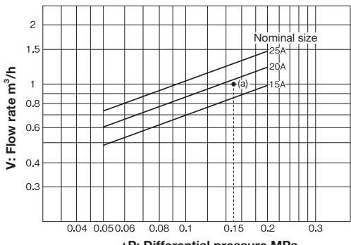
How to use the chart: When selecting the nominal size of a temperature regulator whose inlet pressure, outlet pressure, and flow rate are 0.3 MPa, 0.15 MPa, and 1 m³/h, respectively:
WARNING
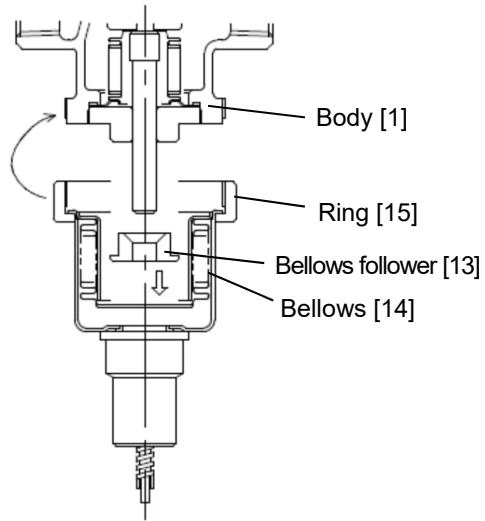
Place the bellows follower, which is packaged with the body, into the bellows with its flat surface facing downward and then screw it into the lower surface of the body by the ring. It makes the assembly easier to loosen the handle in the direction of the “L” position. Be sure not to lose the bellows follower because the product does not function properly without it.
| Scale Reading | 0–35 °C | 25–70 °C | 40–100 °C |
|---|---|---|---|
| 0 | - | - | - |
| 1 | -14 °C | 11 °C | 23 °C |
| 2 | 9 °C | 38 °C | 55 °C |
| 3 | 32 °C | 65 °C | 94 °C |
| 4 | 55 °C | 98 °C | 141 °C |
Note: The table shows the set temperature per scale reading as a guide. Because the temperature varies slightly according to conditions of use, adjust the handle until the desired temperature is obtained.
Temperature does not lower or lowers excessively:
Large error of temperature control:
Outside leakage:
DANGER
Inspection must be done by an experienced professional or valve manufacturer. Completely discharge the pressure inside of the product, piping, and equipment prior to disassembly and inspection. When the fluid is hot, cool down the product to the condition that it can be touched with bare hands.
Yoshitake Control Valves / Self-operated Regulators
OB, GPR, CF, and GD series self-operated regulators for pressure and temperature control without external power.
Explore similar products in our catalog