Feed-Forward Design

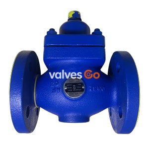
The Yoshitake OB-3G is a direct-acting temperature regulator valve featuring an external pressure type bellows for distinguished temperature resistance. It offers a 15-100°C adjusting range and 0.7 MPa maximum pressure.
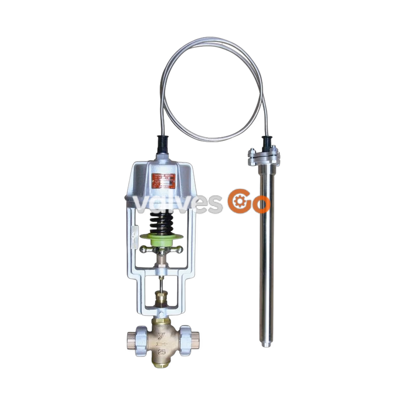
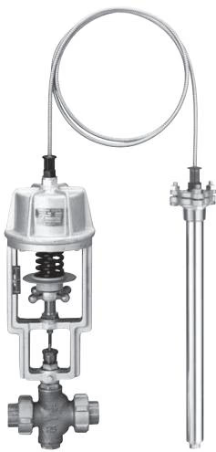
Yoshitake OB-3G is a direct-acting temperature regulator valve designed for both heating and cooling applications. It is equipped with an external pressure type bellows that ensures distinguished temperature resistance, making it highly reliable for controlling cold and hot water, oil, refrigerants, and other non-dangerous fluids. The valve features a dual-valve structure that provides a larger flow rate compared to single-valve models, and it utilizes a union type connection screw for easy piping installation.
| Feature | Specification |
|---|---|
| Application (Cooling) | Cold water, Refrigerant |
| Application (Heated) | Cold and hot water, Oil, Non-dangerous fluid |
| Max. Pressure (Body) | 0.7 MPa |
| Max. Pressure (Thermal bulb) | 1.0 MPa |
| Maximum Temperature | 180°C |
| Temperature Adjusting Range | 15-100°C (For liquid and air) |
| Ambient Temperature | Set temp. +30°C or less |
| Material (Body) | Bronze |
| Material (Valve, valve seat) | Bronze |
| Material (Valve spindle) | Stainless steel |
| Material (Bellows) | Phosphor bronze |
| Material (Thermal bulb) | Stainless steel (with fin for air) |
| Standard Capillary Length | 2 m (Available up to 5 m) |
| Connection | JIS Rc screwed (union joint) |
INFO
| Temperature adjusting range (°C) | Withstand temperature (°C) |
|---|---|
| 15 - 35 | 50 |
| 20 - 40 | 50 |
| 35 - 55 | 70 |
| 40 - 60 | 90 |
| 50 - 70 | 100 |
| 60 - 80 | 110 |
| 70 - 90 | 120 |
| 80 - 100 | 130 |
The term "Withstand temperature" means the temperature from pressure resistance of the bellows.
Depending on capillary length (For liquid and air):
(If the preset temperature is higher than 100°C, add ± 1.0°C. The preset temperature error is the maximum temperature width ranging from the time when the valve closes until the time when the valve starts to open, not the value expressing the control width.)
| Nominal Size | 15A | 20A | 25A | 32A | 40A |
|---|---|---|---|---|---|
| Cv Value | 2 | 2 | 4 | 7 | 10 |
| Valve Seat Leakage | 1.5 | 1.5 | 1.8 | 2.4 | 3.0 |
(Leakage Unit: steam kg/h, water L/h. Measured under the condition of 0.5 MPa or max. pressure at the temperature of "set temperature - 5°C" for cooling.)
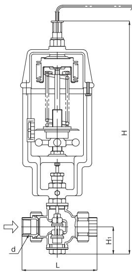
| Nominal size | d | L (mm) | H1 (mm) | H (mm) | Weight (kg) |
|---|---|---|---|---|---|
| 15A | Rc 1/2 | 148 | 55 | 510 | 11 |
| 20A | Rc 3/4 | 148 | 55 | 510 | 11 |
| 25A | Rc 1 | 160 | 60 | 520 | 12 |
| 32A | Rc 1-1/4 | 195 | 60 | 520 | 12 |
| 40A | Rc 1-1/2 | 210 | 65 | 530 | 13 |
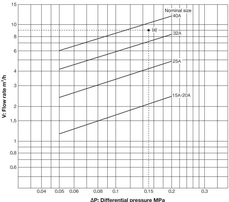
How to use the chart: When inlet pressure is 0.3 MPa, outlet pressure is 0.15 MPa, and flow rate is 9 m³/h, first find the intersection point (a) with the differential pressure (∆P) 0.15 MPa (0.3 MPa – 0.15 MPa) before and after valve and the flow rate 9 m³/h. Since this intersection point (a) locates between nominal sizes 32A and 40A, select the larger one, 40A.
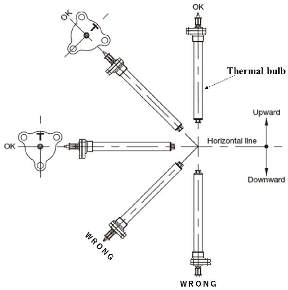
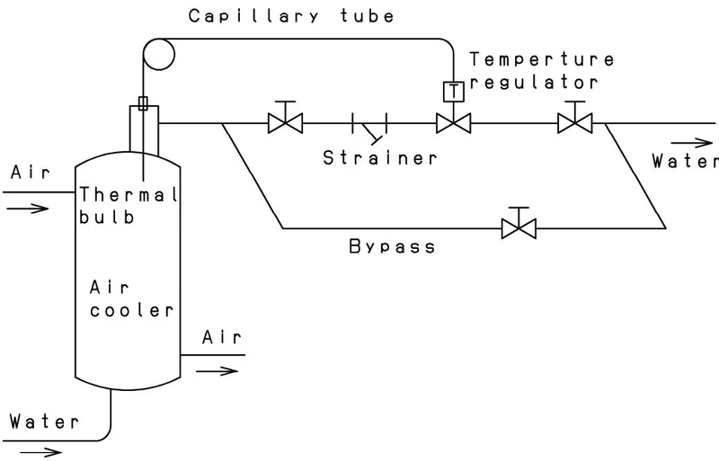
WARNING
TIP
Incorrect adjustment may cause hunting, scale problems or water hammer, and may heavily damage the main parts of the product. Be sure to follow the steps below:
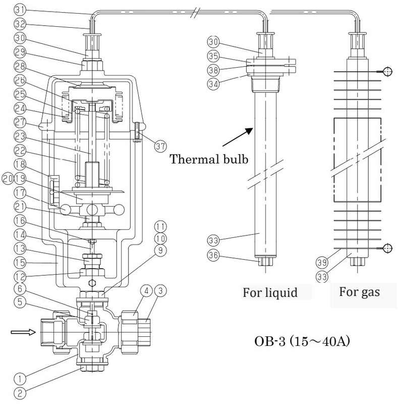
| No. | Name of Parts | Material |
|---|---|---|
| 1 | Body | Bronze |
| 2 | Bottom Cover | Brass |
| 3 | Union Nipple | Bronze |
| 4 | Union Nut | Ductile Cast Iron |
| 5 | Valve | Phosphor Bronze or Bronze |
| 10 | Gland Packing | PTFE |
| 14 | Spindle | Stainless Steel |
| 17 | Handle | Cast Iron |
| 24 | Bellows | Phosphor Bronze |
| 31 | Flexible Tube | Copper Tube |
| 33 | Thermal Element Pipe | Stainless Steel |
(Note: This is a partial list of key components. Refer to the full technical drawing for all 39 parts.)
Yoshitake Control Valves / Self-operated Regulators
OB, GPR, CF, and GD series self-operated regulators for pressure and temperature control without external power.
Explore similar products in our catalog