Ductile Cast Iron

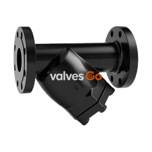
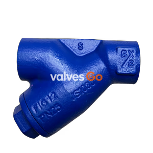
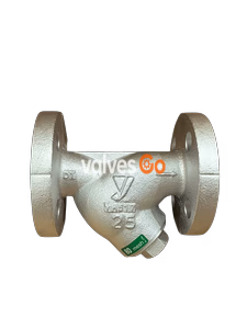
Yoshitake SY-20-10 Y-type strainer for steam, air, water, and oil. Features a cast carbon steel body, stainless steel 80 mesh screen, and JIS 10K RF flanged connection. Max pressure 1.0 MPa, max temperature 260°C.
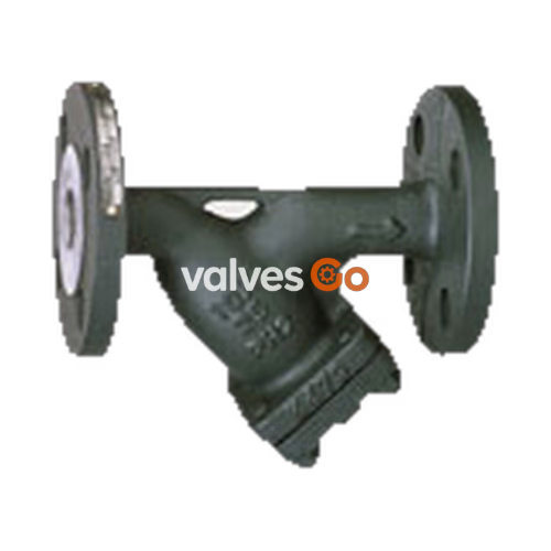
Yoshitake SY-20-10 is a high-flow-rate marine type Y-strainer designed with the largest possible filtration area to minimize flow rate decreases caused by clogging. It is widely used for removing dust, scale, and foreign matter from water, oil, and other fluids, and is especially suited for cooling water and industrial water applications. The strainer features a cast carbon steel body and a standard 80 mesh stainless steel screen.
| Specification | Value |
|---|---|
| Application | Steam, Air, Cold and hot water, Oil, Other non-dangerous fluids |
| Nominal Size | 15A-150A |
| Maximum Pressure | 1.0 MPa |
| Maximum Temperature | 260°C |
| Connection | JIS 10K RF Flanged |
| Body Material | Cast Carbon Steel (SCPH2) |
| Screen Material | Stainless Steel (SUS304) |
| Perforation | φ6-8P (φ6-1.8 holes/cm²) |
| Mesh | 80 mesh (Standard), 20-60 mesh available |
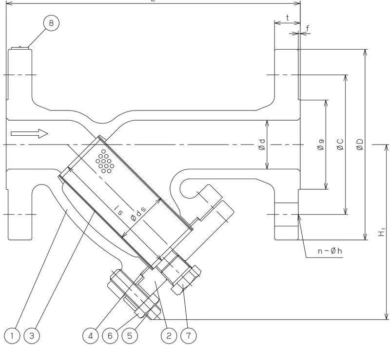
| Size | L | H1 | ds | ls | Plug | Weight (kg) |
|---|---|---|---|---|---|---|
| 15A | 160 | 104 | 25 | 65.5 | R 3/8 | 3.0 |
| 20A | 160 | 113 | 30 | 71.5 | R 3/8 | 3.7 |
| 25A | 180 | 122 | 33 | 76.0 | R 3/8 | 4.8 |
| 32A | 240 | 154 | 55 | 105.0 | R 1/2 | 8.0 |
| 40A | 240 | 154 | 55 | 105.0 | R 1/2 | 8.0 |
| 50A | 260 | 174 | 57 | 112.0 | R 1/2 | 10.5 |
| 65A | 275 | 187 | 74 | 130.0 | R 1/2 | 14.3 |
Note: The nominal size range is up to 150A; this table presents the dimensions available from the truncated source excerpt.
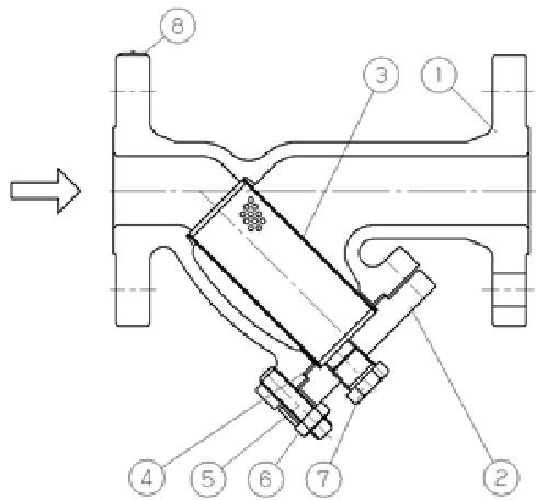
| No. | Name of Parts | Material |
|---|---|---|
| 1 | Body | Cast Steel (SCPH2) |
| 2 | Cover | Cast Steel (SCPH2) |
| 3 | Screen | Stainless Steel (SUS304) |
| 4 | Gasket | Non-Asbestos |
| 5 | Stud Bolt | Steel |
| 6 | Nut | Steel |
| 7 | Plug | Steel |
| 8 | Name Plate | Stainless Steel (SUS) |
The screen (3) removes dust, scale, and other foreign matter from the fluid flowing from the inlet port of the strainer.
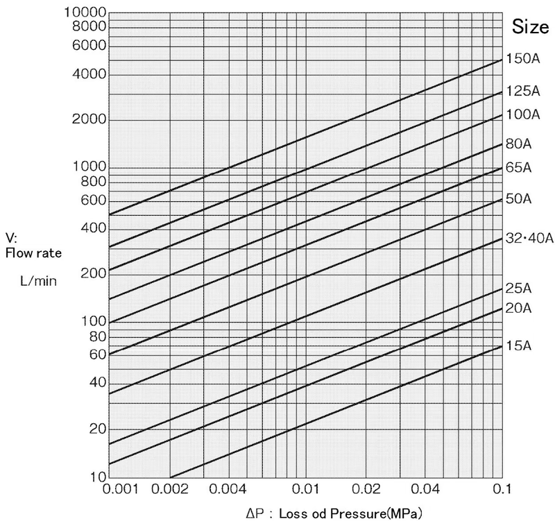
When selecting the nominal diameter of the pipe, consider the fluid kind, maximum flow rate, allowable pressure loss, and installation cost. A smaller diameter pipe lowers piping cost but increases pressure loss and the possibility of abrasion, noise, and vibration. If the pipe diameter is too large, both piping cost and heat loss increase.
Standard Flow Velocity of Fluid
| Fluid | Standard Flow Velocity |
|---|---|
| Water, Oil | 2 ~ 3 m/s (2~4) |
| Steam | 30 ~ 40 m/s (20~40) |
WARNING
Because of heavy weight, hold the valve with lifting equipment while piping. Failure to do so may result in injury due to dropping the valve.
Precautions
Maintenance Space Requirements (H)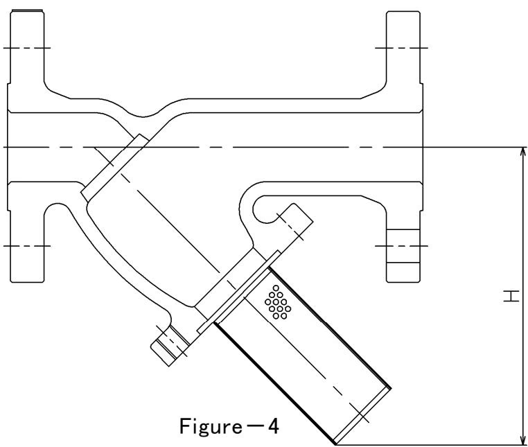
| Size | H (mm) |
|---|---|
| 15A | 146 |
| 20A | 158 |
| 25A | 170 |
| 32A | 223 |
| 40A | 223 |
| 50A | 248 |
| 65A | 276 |
| 80A | 342 |
| 100A | 393 |
| 125A | 467 |
| 150A | 585 |
WARNING
Completely discharge internal pressure from the strainer, lines, and equipment, and cool the strainer down to a level where you can touch it with bare hands before disassembly and inspection. Since the screen is heavy, when extracting the screen from the body, secure it properly with lifting devices.
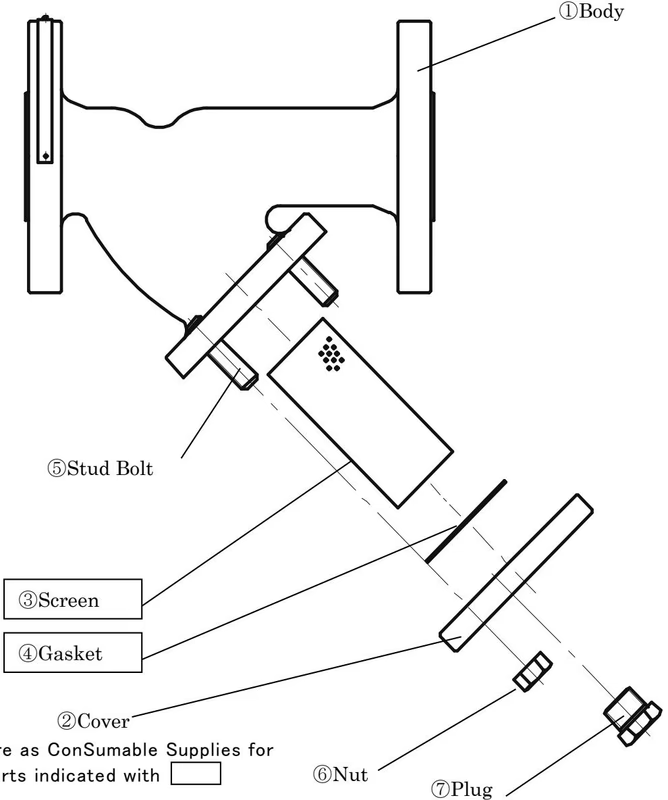
Disassembly Procedure After confirming that the remaining pressure is relieved from the strainer, remove the bolts from the cover and the gasket, and remove the cover from the body. Extract the screen from the body and clean it with compressed air or cleanser.
Assembly Procedure Clean the gasket contacting surface of the body and cap, and fit a new gasket to the cap. Fit the screen to the body and the cap before tightening the nut. Tighten the bolts evenly on each bolt in turn of diagonal position.
Troubleshooting
| Trouble Condition | Cause of Trouble | Countermeasure and Remedy |
|---|---|---|
| No fluid flows | 1. Screen is clogged up. 2. Stop valves at inlet and/or outlet side are shut. | 1. Disassemble and clean the screen. 2. Open stop valves. |
| Pressure loss is excessive | 1. Screen is clogged up. 2. Pressure gauge is damaged. | 1. Disassemble and clean the screen. 2. Renew the pressure gauge. |
| Outer leakage occurs | 1. Gasket has deterioration. | 1. Replace the gasket. |
Yoshitake Instrumentation / Strainers
SY, SU, SW, and ST series strainers for removing line debris and protecting downstream valves and equipment.