PN16
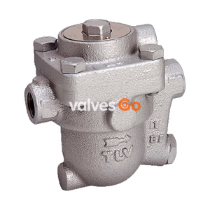
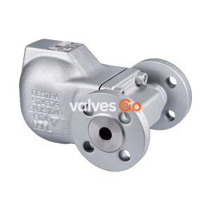
Yoshitake TSF-10 series float steam trap with built-in thermostatic air vent. Supports all flow directions, ductile cast iron body, max temperature 220℃, up to 2.1 MPa.
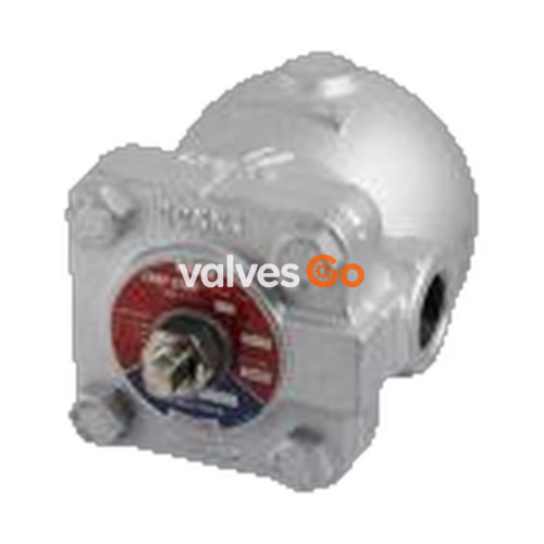
Yoshitake TSF-10 and TSF-10F are float steam traps featuring an incorporated thermostatic air vent. By turning the cock, the product can be installed in various flow directions such as horizontal or vertical piping without disassembly. Since all main parts are mounted on the cover, inspection and parts replacement can be easily conducted without detaching the valve body from the pipeline.
| Model | TSF-10 | TSF-10F | TSF-11 | TSF-11F |
|---|---|---|---|---|
| Nominal size | 15A-25A | 15A-25A | 25A-50A | 25A-50A |
| Application | Steam condensate | Steam condensate | Steam condensate | Steam condensate |
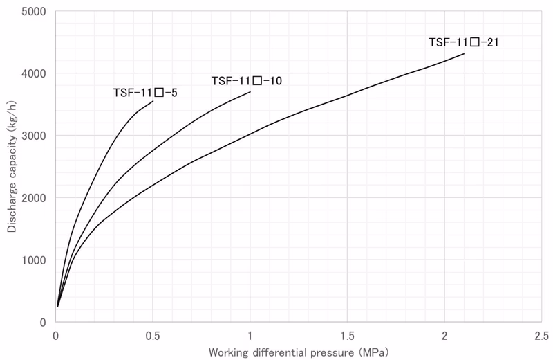
| Working pressure | TSF-1□□-5: 0.01-0.5 MPa TSF-1□□-10: 0.01-1.0 MPa TSF-1□□-21: 0.01-2.1 MPa | TSF-1□□-5: 0.01-0.5 MPa TSF-1□□-10: 0.01-1.0 MPa TSF-1□□-21: 0.01-2.1 MPa | TSF-1□□-5: 0.01-0.5 MPa TSF-1□□-10: 0.01-1.0 MPa TSF-1□□-21: 0.01-2.1 MPa | TSF-1□□-5: 0.01-0.5 MPa TSF-1□□-10: 0.01-1.0 MPa TSF-1□□-21: 0.01-2.1 MPa |
| Max. temperature | 220℃ | 220℃ | 220℃ | 220℃ |
| Body Material | Ductile cast iron | Ductile cast iron | Ductile cast iron | Ductile cast iron |
| Float Material | Stainless steel | Stainless steel | Stainless steel | Stainless steel |
| Valve, Valve seat | Stainless steel | Stainless steel | Stainless steel | Stainless steel |
| Connection | JIS Rc screwed, NPT screwed | JIS 10K FF, JIS 20K FF | JIS Rc screwed, NPT screwed | JIS 10K FF, JIS 20K FF |
| Flow direction | All directions | All directions | All directions | All directions |
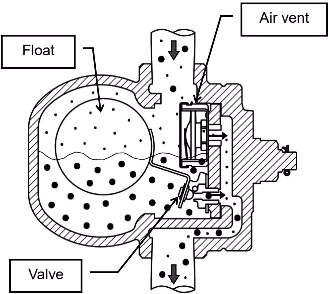
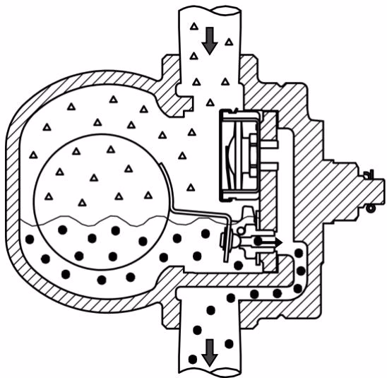
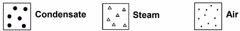
1. Start-up of the operation At start-up, since the float is down, the valve is closed. In this state, air in the system and piping is discharged out through the air vent which is opened. When condensate flows into the product, the float lifts up and opens the valve, and then discharges condensate. Air is continuously discharged out from the air vent.
2. Condensate discharging operation When steam flows into the product, internal pressure of the air vent rises by steam temperature, and the air vent closes. According to the amount of condensate inflow, the float position moves up and down changing the opening degree of the valve, and thus condensate is continuously discharged. The float moves down and the valve closes when condensate inflow stops.
3. Air vent operation When air or non-condensable gas flows into the product, it accumulates in the upper part of the product. When temperature of air or noncondensable gas decreases with condensate inflow, the air vent opens and discharges it to outside of the product. Then, operations 2 and 3 repeats according to the inflow amount of condensate and air.


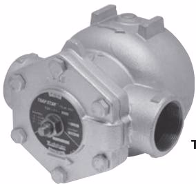
TSF-10
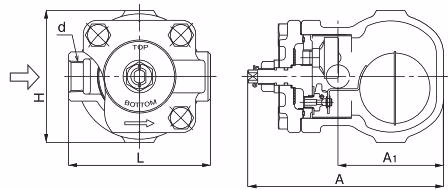
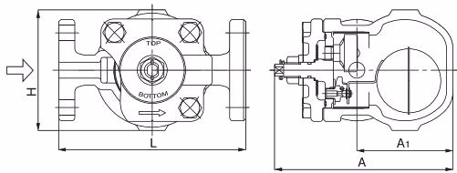
| Nominal size | d | L (mm) | A (mm) | A1 (mm) | H (mm) | Weight (kg) |
|---|---|---|---|---|---|---|
| 15A | Rc 1/2 | 121 | 167 | 90 | 113 | 3.6 |
| 20A | Rc 3/4 | 121 | 167 | 90 | 113 | 3.6 |
| 25A | Rc 1 | 145 | 167 | 90 | 113 | 4.0 |
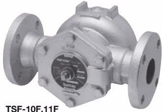
TSF-10F
| Nominal size | d (mm) | L (mm) | A (mm) | A1 (mm) | H (mm) | Weight (kg) |
|---|---|---|---|---|---|---|
| 15A | 15 | 175 | 167 | 90 | 113 | 5.0 |
| 20A | 20 | 195 | 167 | 90 | 113 | 5.8 |
| 25A | 25 | 215 | 167 | 90 | 113 | 7.1 |
Adjust direction of the nameplate
Adjust direction of the name plate in no pressure condition after installation. Fix the cock with spanner and loosen the nut. Turn the cock and adjust direction of the name plate to position "TOP" and "BOTTOM" signs on upside and downside respectively. Fix the cock with spanner and fasten the nut after adjustment.
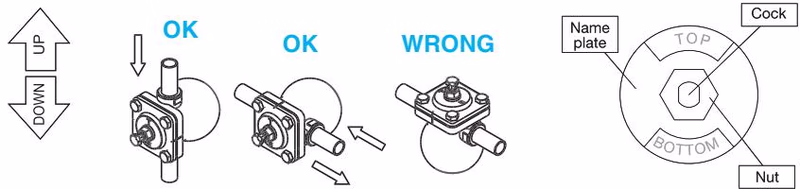
*In case of Bottom to Top, Please apply that shorten the vertical piping before the trap to open and discharge easily of trap in the condition of using upward flow direction.
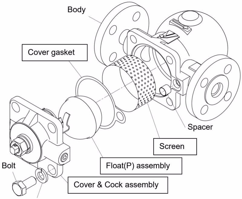
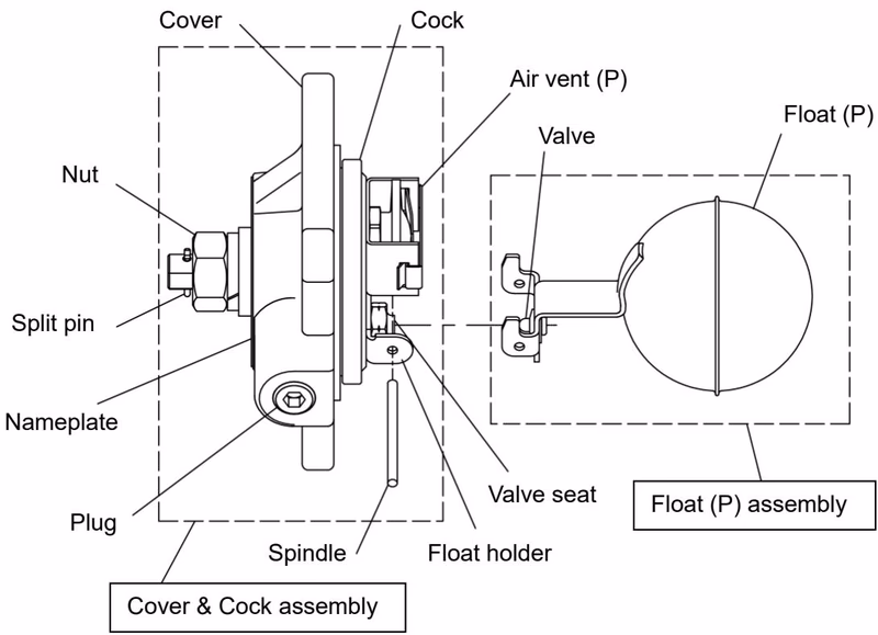
Consumable Supply
The parts shown in the rectangle boxes are available as consumable supply. The air vent (P) cannot be removed from the cock. Do not remove the plug from the cover except when disposing.