PN16
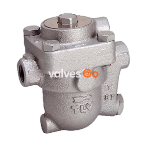
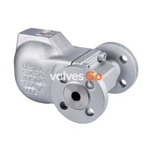
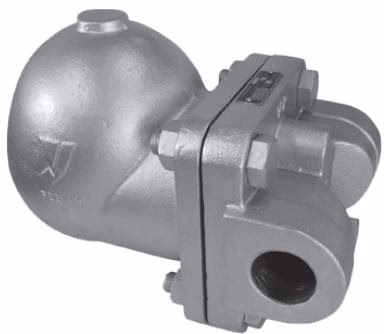
Yoshitake TSF-12 lever float steam trap with ductile cast iron body and stainless steel internals. Features a high-pressure air vent for quick start-up and high discharge capacity for steam condensate systems up to 230℃.
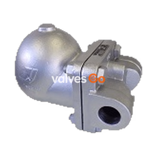
Yoshitake TSF-12 is a high-capacity lever float steam trap designed for steam condensate applications. It features a ductile cast iron body with stainless steel internal components, ensuring excellent corrosion resistance and durability. The trap is equipped with a high-pressure air vent to quickly exhaust air in the steam piping system, significantly shortening equipment start-up time.
| Specification | Value |
|---|---|
| Model | TSF-12 |
| Nominal Size | 40A, 50A |
| Application | Steam condensate |
| Max. Temperature | 230℃ |
| Body Material | Ductile cast iron |
| Float, Valve, Valve Seat | Stainless steel |
| Connection | JIS Rc screwed, NPT screwed |
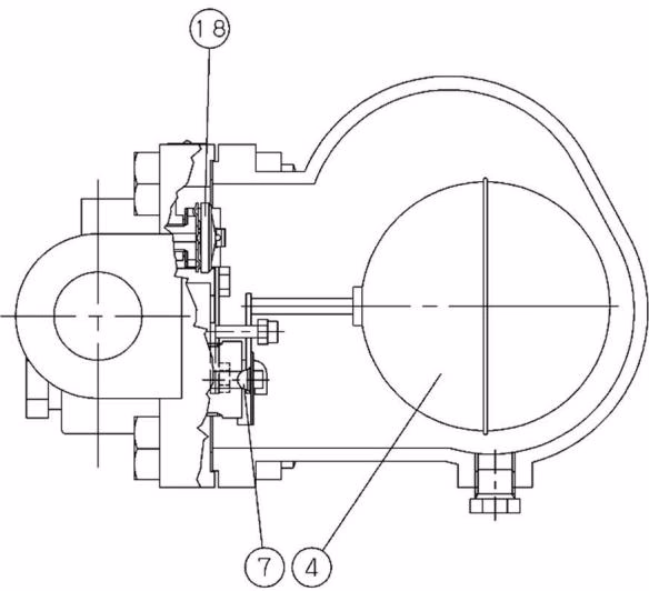 At start-up, since the float is down, the valve is closed. Air in the system and piping is discharged out through the opened air vent. When condensate flows into the product, the float lifts up, opens the valve, and discharges condensate. Air is continuously discharged out from the air vent. When steam flows into the product, the internal pressure of the air vent rises by steam temperature, and the air vent closes. The float position moves up and down changing the opening degree of the valve according to the amount of condensate inflow.
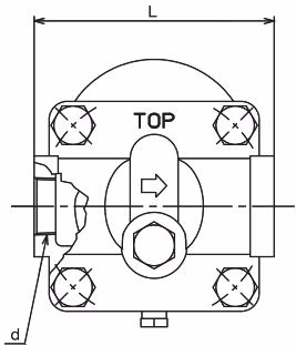
| Nominal Size | d | L (mm) | A (mm) | A1 (mm) | H (mm) | Weight (kg) |
|---|---|---|---|---|---|---|
| 40A | Rc 1-1/2 / NPT 1-1/2 | 200 | 308 | 266 | 228 | 21.7 |
| 50A | Rc 2 / NPT 2 | 200 | 361 | 319 | 285 | 24.6 |
Safety Factor
The discharge capacity shown in the charts is the maximum value. When designing a system, select a steam trap with a sufficient safety factor (at least twice).
40A Model: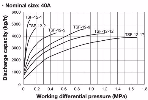
50A Model: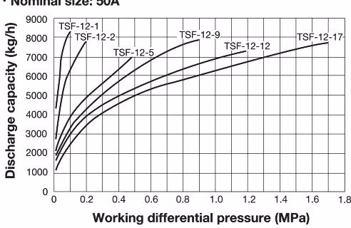
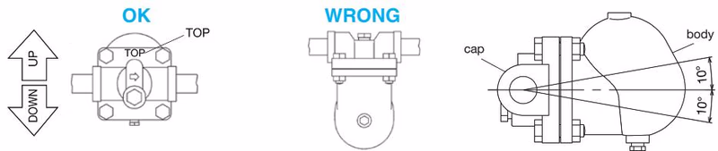
Installation Posture
Confirm the direction of fluid flow matches the inlet and outlet sides of the product. Setting the product in wrong directions prevents proper functioning. Check installation posture; do not tilt the product during use. The allowable tilt from the horizontal line is within ±10°.
Discharge Internal Pressure
Completely discharge internal pressure of the product, piping, and equipment, and cool down the product prior to disassembly or maintenance. Do not touch the product with bare hands while it operates.
| Trouble | Cause | Remedy |
|---|---|---|
| Condensate is not discharged | Blockage of foreign substances in the valve seat. | Disassemble and clean it. |
| Float is broken. | Change into new one. | |
| Abnormal pressure rising (freezing, water hammer). | Replace the product. | |
| Steam locking. | Change the piping system layout. | |
| Product is in wrong posture. | Adjust direction of the mark "TOP" to upward. | |
| Continuous blowout | Foreign substances stuck on valve, valve seat or air vent. | Disassemble and clean them. |
| Abrasion or scratches on internals. | Replace the parts. | |
| Insufficient capacity. | Replace with a model of sufficient capacity. | |
| Steam leakage | Leakage due to loosening of the bolt. | Replace the cover gasket and retighten. |
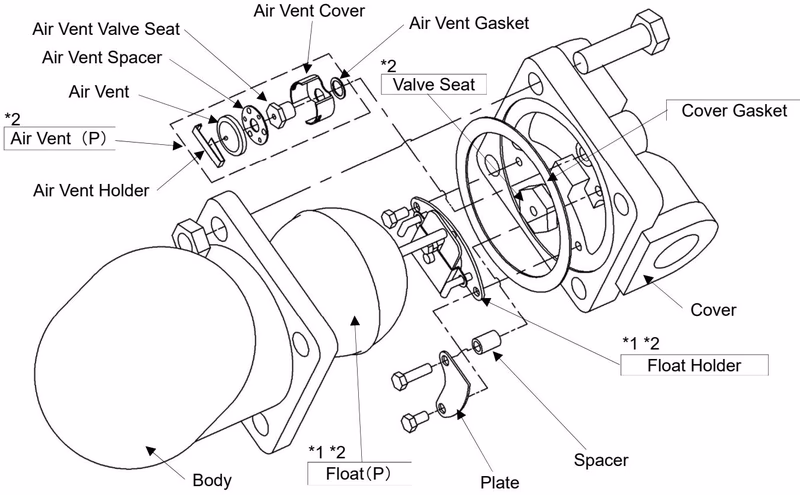
Parts available as consumable supplies include the cover gasket, float assembly, valve seat, and air vent components.