


PN16

Yoshitake TSF-8F and TSF-8 float steam traps for steam condensate. Features ductile cast iron body, stainless steel internals, built-in strainer, and max temperature of 220°C.
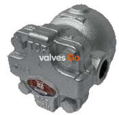
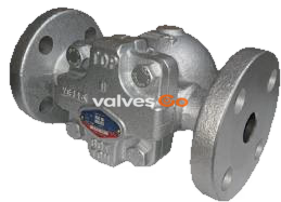
Yoshitake TSF-8F and TSF-8 float steam traps are designed for efficient steam condensate discharge. They feature a ductile cast iron body and stainless steel internal components, providing excellent corrosion resistance and durability. The traps utilize the specific gravity difference between steam and condensate to provide stable and highly efficient continuous discharge.

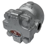
| Model | TSF-8 | TSF-8F |
|---|---|---|
| Nominal size | 15A, 20A, 25A | 15A, 20A, 25A |
| Application | Steam condensate | Steam condensate |
| Working pressure (Max. diff.) | TSF-8-5: 0.01-0.5 MPa (0.5 MPa) TSF-8-10: 0.01-1.0 MPa (1.0 MPa) TSF-8-21: 0.01-2.1 MPa (2.1 MPa) | TSF-8F-5: 0.01-0.5 MPa (0.5 MPa) TSF-8F-10: 0.01-1.0 MPa (1.0 MPa) TSF-8F-21: 0.01-2.1 MPa (2.1 MPa) |
| Max. temperature | 220°C | 220°C |
| Body Material | Ductile cast iron | Ductile cast iron |
| Float Material | Stainless steel | Stainless steel |
| Valve, valve seat Material | Stainless steel | Stainless steel |
| Connection | JIS Rc screwed, NPT screwed | JIS 10K/20K FF flanged, EN PN25 RF, ASME 150lb/300lb RF |
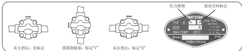
| Flow direction | Left to Right (Standard) | Left to Right (Standard) |
Flow Direction Options
The standard flow direction is from left to right. Suffix "V" is used for "Top to Bottom" flow, and "R" for "Right to Left" flow.
| Flow Direction | Mark |
|---|---|
| Left to Right (Standard) | Blank |
| Top to Bottom | V |
| Right to Left | R |
TSF-8 (Screwed)
| Size | d | L | A | A1 | H | Weight (kg) |
|---|---|---|---|---|---|---|
| 15A | Rc 1/2 | 121 | 147 | 90 | 113 | 3.7 |
| 20A | Rc 3/4 | 121 | 147 | 90 | 113 | 3.7 |
| 25A | Rc 1 | 145 | 147 | 90 | 113 | 4.1 |
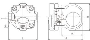
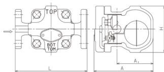
TSF-8F (Flanged)
| Size | d | L | A | A1 | H | Weight (kg) |
|---|---|---|---|---|---|---|
| 15A | 15 | 175 | 147 | 90 | 113 | 5.2 |
| 20A | 20 | 195 | 147 | 90 | 113 | 6.0 |
| 25A | 25 | 215 | 147 | 90 | 113 | 7.1 |
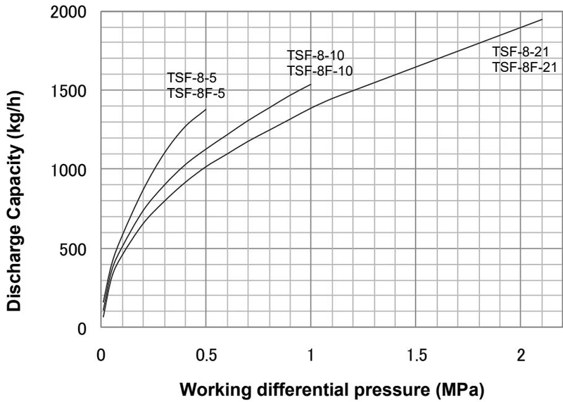
1. Start-up of the operation At start-up, since the float is down, the valve is closed. Air in the system and piping is discharged out through the air vent which is opened. When condensate flows into the product, the float lifts up and opens the valve, discharging condensate. Air is continuously discharged out from the air vent.
2. Condensate discharging operation When steam flows into the product, internal pressure of the air vent rises by steam temperature, and the air vent closes. According to the amount of condensate inflow, the float position moves up and down changing the opening degree of the valve, continuously discharging condensate. The float moves down and the valve closes when condensate inflow stops.
3. Air vent operation When air or non-condensable gas flows into the product, it accumulates in the upper part. When temperature decreases with condensate inflow, the air vent opens and discharges it to the outside. Operations 2 and 3 repeat according to the inflow amount of condensate and air.
Installation Warnings
Conduct daily and periodic inspections in order to maintain the optimal performance of the product.
Daily inspection (once a day)
Periodic inspection (once a year)
Troubleshooting
| Trouble | Cause | Remedy |
|---|---|---|
| Condensate is not discharged. | 1. Blockage of foreign substances in a discharge hole. 2. The screen is clogging. 3. The float (P) is damaged. 4. Breakage due to abnormal pressure rising. 5. Steam locking. 6. "TOP" and "BOTTOM" signs are in wrong positions. | 1. Disassemble and clean it. 2. Disassemble and clean it. 3. Replace it with a new one. 4. Replace the product and use within working pressure. 5. Change the piping system layout. 6. Adjust direction of the name plate. |
| Continuous blowout. | 1. Foreign substances stuck on valve, seat or air vent. 2. Abrasion or scratches on the parts. 3. Insufficient capacity of the product. 4. "TOP" and "BOTTOM" signs are in wrong positions. | 1. Disassemble and clean them. 2. Replace the parts with new ones. 3. Replace with a model of sufficient capacity. 4. Adjust direction of the name plate. |
| Steam leakage. | 1. Leakage due to loosening of the bolt. 2. Leakage due to abnormal pressure rising. | 1. Replace cover gasket and retighten bolt. 2. Replace the product and use within working pressure. |
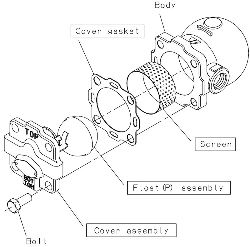
Disassembly
Reassembly
Yoshitake Steam Traps / Float Steam Traps
TF and TSF series float steam traps for continuous condensate drainage in steam systems.





