


PN16

Yoshitake TSF-13, TSF-13F, and TSF-13CF float steam traps featuring a double-port structure, large discharge capacity, and stainless steel internal parts for steam condensate applications.
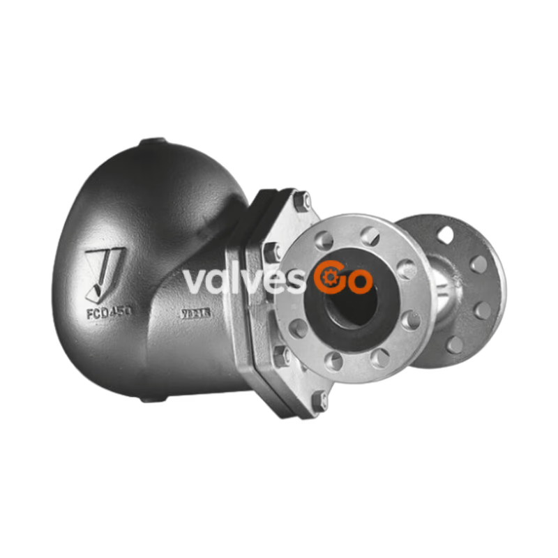
The Yoshitake TSF-13 series float steam traps are designed for steam condensate applications, featuring a double-port structure that ensures reliable performance and a large discharge capacity. The series includes the standard TSF-13 (screwed), TSF-13F (flanged), and the TSF-13CF (cast steel flanged) models. All main internal parts, such as valves, seats, air vents, and floats, are constructed from stainless steel to offer excellent corrosion resistance and durability.
| Model | TSF-13 | TSF-13F | TSF-13CF |
|---|---|---|---|
| Nominal size | 40A, 50A | 40A, 50A | 40A, 50A |
| Application | Steam Condensate | Steam Condensate | Steam Condensate |
| Max. working pressure | 1.6 MPa | 1.0 MPa / 1.6 MPa | 1.0 MPa / 1.6 MPa / 3.2 MPa |
| Max. differential pressure (ΔPMX) | 0.5 / 1.0 / 1.4 MPa | 0.5 / 1.0 / 1.4 MPa | 0.5 / 1.0 / 3.2 MPa |
| Min. differential pressure | 0.01 MPa | 0.01 MPa | 0.01 MPa |
| Max. temperature | 220°C | 220°C | 240°C |
| Body Material | Ductile cast iron | Ductile cast iron | Cast steel (WCB) |
| Float / Valve Material | Stainless steel | Stainless steel | Stainless steel |
| Connection | JIS Rc / NPT screwed | JIS 10K/20K RF, ASME 150/300, EN PN16/25 | JIS 30K RF, ASME 150/300, EN PN25/40 |
Installation Caution
Install a strainer (mesh size of 80 or more is recommended) at the inlet side of the product. Due to the double-port structure, foreign substances stuck on the valve and valve seat may cause significant steam leakage.
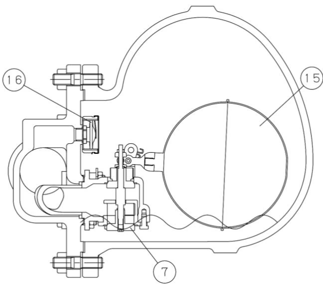
At start-up: Since the float is down, the valve set is closed. In this state, air in the system and piping is discharged out through the air vent which is opened.
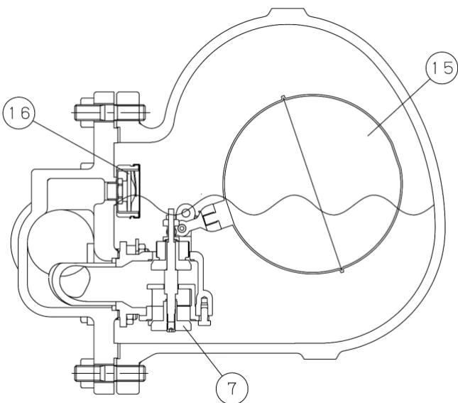
During condensate inflow: When condensate flows into the product, the float lifts up and opens the valve set, and then discharges condensate. Air is continuously discharged out from the air vent. When steam flows into the product, internal pressure of the air vent rises by steam temperature, and the air vent closes. According to the amount of condensate inflow, the float position moves up and down changing the opening degree of the valve set, and thus condensate is continuously discharged.
The discharge capacity shown in the charts below is the maximum value. In designing a system, select a steam trap with a sufficient safety factor (at least twice). That is, for example, if a discharge capacity of 2000 kg/h is required, select a steam trap capable of discharging more than 4000 kg/h (maximum discharge).
Maximum Continuous Discharge Capacity of 40A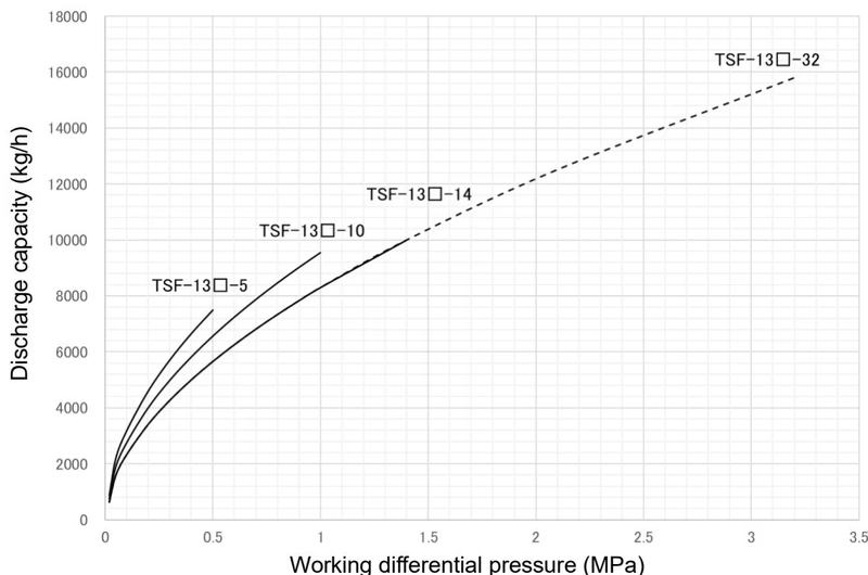
Maximum Continuous Discharge Capacity of 50A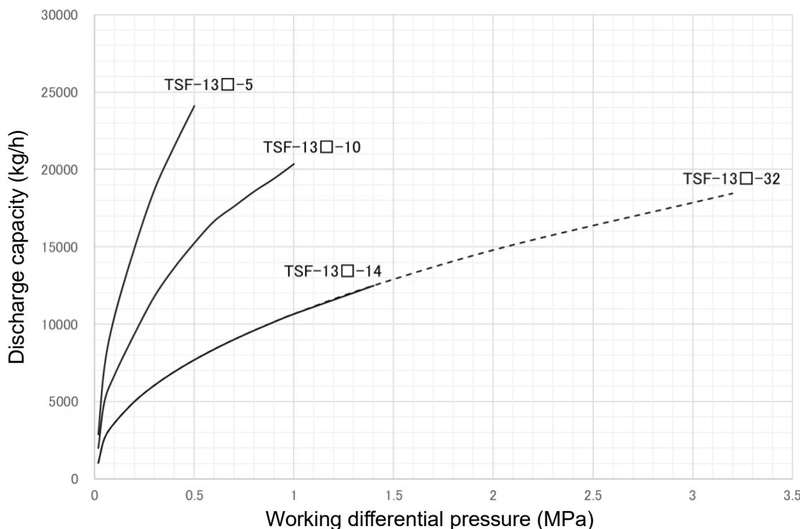
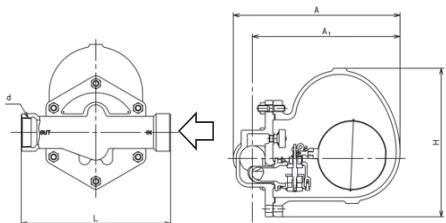
TSF-13 (Screwed)
| Nominal size | Connection | d | L | A | A1 | H | Weight |
|---|---|---|---|---|---|---|---|
| 40A | JIS Rc | Rc 1-1/2 | 270 | 313 | 281 | 290 | 19 |
| 50A | NPT | Rc 2 | 300 | 328 | 291 | 290 | 20 |
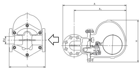
TSF-13F (Flanged)
| Nominal size | Connection | d | L | A | A1 | H | Weight |
|---|---|---|---|---|---|---|---|
| 40A | JIS 10KRF/20KRF | 40 | 228 | 423 | 353 | 290 | 24 |
| 40A | EN 1092 PN16 or PN25 | 40 | 230 | 428 | 353 | 290 | 24.5 |
| 40A | ASME Class 150 | 40 | 221 | 416 | 353 | 290 | 23 |
| 40A | ASME Class 300 | 40 | 221 | 431 | 353 | 290 | 25.7 |
| 50A | JIS 10KRF/20KRF | 50 | 239 | 436 | 358 | 290 | 25 |
| 50A | EN 1092 PN16 or PN25 | 50 | 230 | 441 | 358 | 290 | 25.3 |
| 50A | ASME Class 150 | 50 | 220 | 433 | 358 | 290 | 24.5 |
| 50A | ASME Class 300 | 50 | 239 | 441 | 358 | 290 | 26.8 |
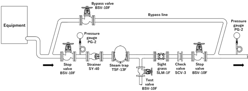
Piping Guidelines
Installation Posture
The mounting position of the product is horizontal piping. Do not tilt the product during use. Do not install in vertical piping. Allowable tilt from horizontal line is within ±5°. Support the product cover when it is necessary.
Conduct daily and periodic inspections in order to maintain the optimal performance of the product.
| Trouble | Cause | Remedy |
|---|---|---|
| Condensate is not discharged | 1. Blockage of foreign substances in the valve seat. 2. Float is broken. 3. Breakage as a result of abnormal pressure rising. 4. Steam locking. 5. Product is in wrong posture. | 1. Clean the valve set. 2. Change it into new one. 3. Replace the product with new one. 4. Change the piping system layout. 5. Install it correctly. |
| Continuous blowout | 1. Foreign substances stuck on valve or valve seat. 2. Scratches on the valve or valve seat. 3. Insufficient capacity of the product. 4. Product is in wrong position. | 1. Clean the valve set. 2. Replace the valve set. 3. Replace the product with another model of sufficient capacity. 4. Install it correctly. |
| Steam leakage | 1. Leakage due to loosening of the nut fixing the body and cover, or damage due to deterioration of body gasket. 2. Leakage as a result of abnormal pressure rising. | 1. Replace the body gasket with new one, and retighten the nut. 2. Replace the product with new one. |
40A Exploded Drawing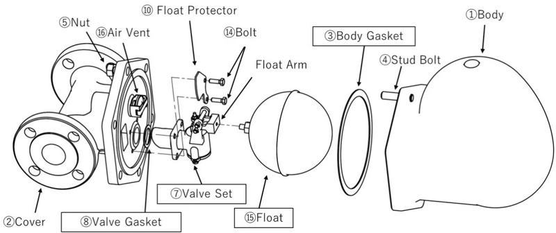
50A Exploded Drawing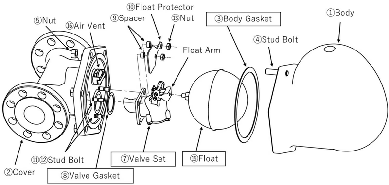
Note: The Air Vent cannot be removed from the Cover. The Valve Set cannot be disassembled.
Parts List:
Disassembly:
Reassembly:
If you need the product with Steam Lock Release (SLR), please let us know when you purchase. It cannot be attached to the standard product later. Steam locking occurs when the pipe to the trap is filled with steam and the steam prevents condensate from flowing into the trap. The SLR bypasses the Air Vent to discharge steam and prevent steam locking.
How to use SLR: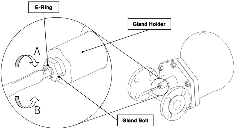
How to replace SLR: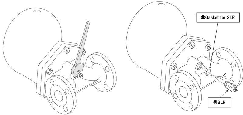
Yoshitake Steam Traps / Float Steam Traps
TF and TSF series float steam traps for continuous condensate drainage in steam systems.





